An Op-Amp Experimenter Board
A typical lab-based Electrical Engineering 101 class will start with the very basics: lectures on resistors, capacitors, inductors, diodes, and how to analyze basic circuits using Kirchhoff’s laws. The labs for these topics usually employ a device to which polar opposites simultaneously apply: A blessing AND a curse, love AND hate, limitless playground for electronic exploration AND the bane of an EE student’s existence. What is this wonderous, terrible device? The solderless breadboard.
We won’t dive into too many details about solderless breadboards here, except to say that they absolutely do have their place and aren’t going away any time soon. They’re invaluable for getting a feel for what electronic components feel like physically, constructing one’s first few circuits while allowing components to be re-used, and getting to the electronic equivalent of “Hello, World!” – lighting an LED (don’t forget the series resistor!). But after those first few 3, 4, 5, or 6 component circuits such as the 2nd order lowpass filter1 shown in Figure 1, the probability of connection errors, short circuits, open connections, and worst of all – intermittent connections, skyrockets.
 Figure 1. Typical “Simple” Breadboard Circuit. (Image source: Analog Devices)
As the complexity and component count of a circuit increase, there is a decision point at which breadboards become impractical2, and it becomes technically essential and economically viable to produce a circuit board. Thanks to the profusion of low-cost, free, and open-source layout software, coupled with low-cost circuit board manufacturers, that decision point has dropped to a ridiculously low level of complexity. It is now possible to watch a few instructional videos, download free layout software, design a board, and have it show up in the mail a week later, for single-digit U.S. dollars. This represents an opportunity for educators and students, so let’s skip any thought experiments and exercise a real example.
After themost basic circuits – voltage dividers, simple RC filters, diodes, and a transistor amplifier or two, the next component a student often encounters is an operational amplifier, or “op-amp”. The (purely analog) op-amp is an extremely versatile component. Even in 2023 with the attention going to artificial intelligence (AI), computer science, digital this, software that, there will always be small signals from the physical world that must be amplified, weak signals that need to be made stronger, often to drive an analog-to-digital converter (ADC) after which the signal lives purely in the digital domain. The opposite case is also true – signals from the digital world will be converted to analog, amplified, and passed to a radio transmitter, speaker, earbud, or display, for eventual consumption by (very much analog) humans.
The first few op-amp circuits a student will build are not terribly complicated, consisting of the op-amp itself, power supply bypass capacitors (don’t forget those!), and a few passive components that determine the function. Examples include:
- Voltage follower/unity gain buffer
- Gain of -1 (analog inverter)
- Gain of +2
- Other inverting and noninverting gains
- Difference amplifier
- Integrator (and lowpass filters)
- Differentiator (and high-pass filters)
Any one of these circuits can be constructed on a breadboard with a high probability of success. But across all circuits, across all students in an afternoon lab session, there will be frustrations – and in the worst case scenario – magic smoke3 exiting the op-amp.
Furthermore, configurations are selected by jumpers, allowing a student to easily switch between functions to build intuition faster – for example, switching back and forth between inverting and noninverting gains, or between a differentiator and integrator.
The circuit in Figure 2 (parts list here) was designed to allow all of these configurations to be tested, measured, and explored with 100% chance of success, at a total cost of single digit dollars. You can also get the circuit board files at GitHub and even order the board through DigiKey’s DKRed or PCB Builder services.
 Figure 2a. Op-Amp Experimenter Kicad Schematic. (Image source: Analog Devices)
 Figure 2b. Op-Amp Experimenter LTspice Schematic for Simulation. (Image source: Analog Devices)
 Figure 2c. Op-Amp Experimenter Circuit Board. (Image source: Analog Devices)
Several op-amp styles are accommodated, and individual devices may be swapped by installing sockets in the board. Single and dual op-amps have standard 8-pin pinouts. The extra pins on a single op-amp serve various functions, most commonly offset adjustment via a potentiometer with its wiper tied to one of the supply rails; this function is fully supported. A central SIP socket accommodates a discrete transistor op-amp described in this Active Learning Exercise.
Before heading to the workbench, it is instructive to work through the circuits on paper, calculating the expected behavior based on the selected components. An LTspice simulation is provided with all component values entered, providing another means for predicting circuit behavior, including transient (time domain) and AC (frequency domain) response4.
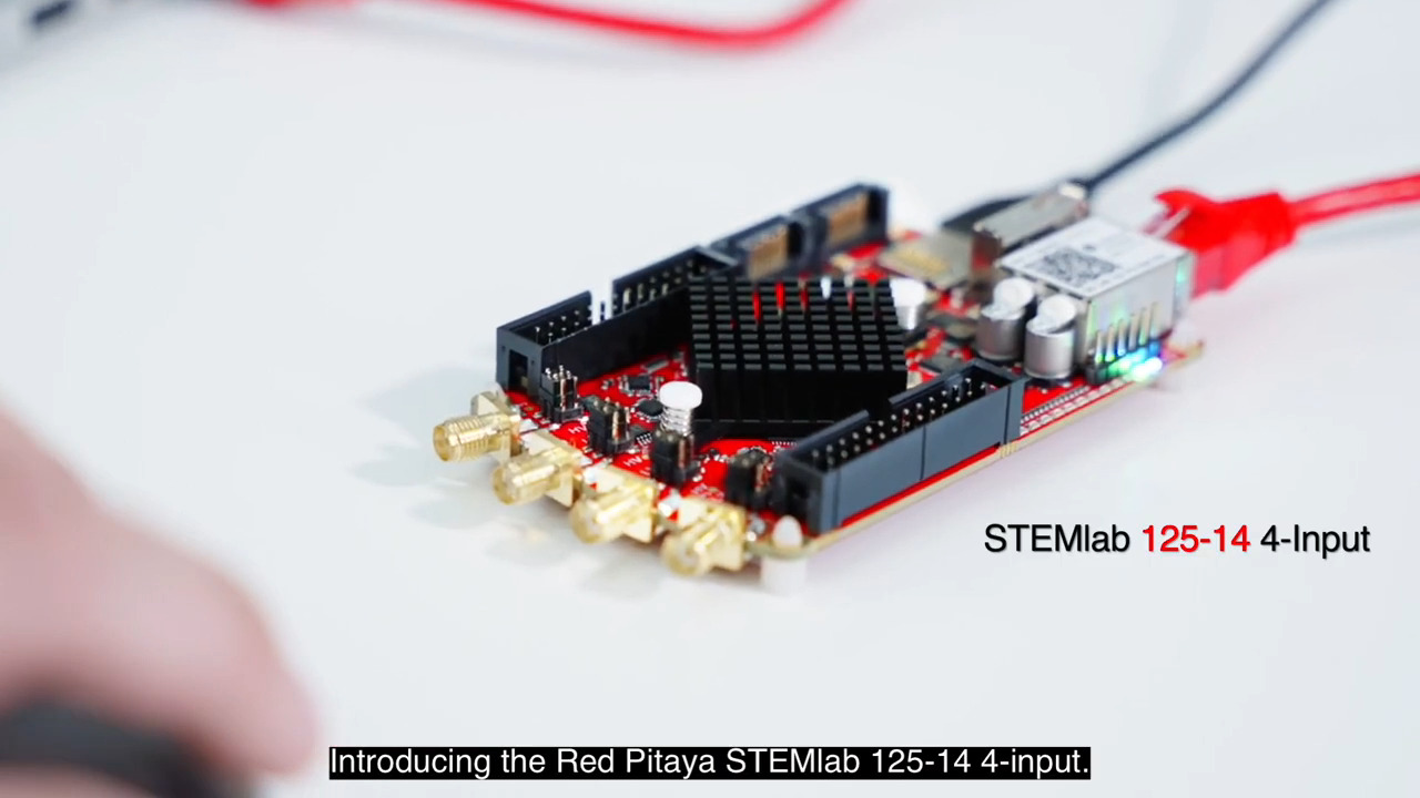
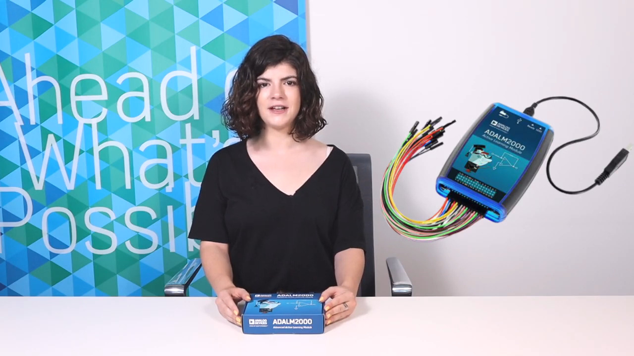
And finally, let’s throw the power switch and see what the circuit does in real life. We’ll use Analog Device’s ADALM2000 here, but the board is designed to be used with almost any bipolar benchtop power supply, signal generator, and oscilloscope, as well as other multifunction test instruments like Red Pitaya’s STEMlab board.
We’re starting with the OP97 amplifier included in the ADALP2000 parts kit, which has a very wide supply range from ±2.25 V to ±20 V, and the ADALM2000’s power supply outputs are set to ±5 V accordingly. We’ll configure the board for one of the more interesting circuits, the difference amplifier, and apply a 1 kHz, 1 Vp-p sinewave to the noninverting input, and a 100 Hz, 1 V sawtooth wave to the inverting input. This waveform allows us to unambiguously observe the polarity inversion of the inverting input, as shown in Figures 3a (LTspice simulation) and 3b (measured results). Channel 1 (orange) is the op-amp’s output, and Channel 2 is the inverting input to the circuit.
 Figure 3a. Difference Amplifier LTspice Simulation. (Image source: Analog Devices)
 Figure 3b. Difference Amplifier Measured Results. (Image source: Analog Devices)
Full instructions for several additional exercises are posted at Operational Amplifier Experimenter Board for the ADALM2000 and Op Amp Experiment Practical Session (Click arrow in the link for detailed setup) for Red Pitaya STEMlab. All circuit board design files (in KiCAD format) and Gerber files are released under the terms of the Creative Commons BY-SA license; links are the associated exercise pages.
Now that the circuit is up and running, a student (or practicing engineer that wants a little refresher) can flip back and forth between the other configurations, exploring expected behavior when all the rules are followed, and just as importantly, the limitations when those rules are broken – output clipping, input common-mode range, bandwidth limitations, and a myriad of other little subtleties that make analog electronics so fun – without having to worry about errors in translating schematics to breadboard connections, shorts, opens, or loose connections. There will be plenty of opportunities for that sort of thing later, both in the university lab and in real life.
Footnotes:
1 - https://wiki.analog.com/university/courses/electronics/electronics-lab-active-filter
2 - Apparently this engineer didn’t get that memo: https://eater.net/8bit/
3 – See: https://en.wikipedia.org/wiki/Magic_smoke
4 – The author has no opinion on whether it’s better to do hand calculations, simulation, or bench testing first. Most real-world development and debug involves iterating between the three in various orders anyway.

Have questions or comments? Continue the conversation on TechForum, DigiKey's online community and technical resource.
Visit TechForum