Advanced Materials Allow Bandpass Filters to Meet Higher Frequency Satellite Comms Requirements
Satellite communication (satcom) is shifting to higher frequency bands in the search for more bandwidth and throughput. Bandwidth in the traditional L (1 to 2 gigahertz (GHz)), C (4 to 8 GHz), and X (7 to 11 GHz) bands is fast being used up, so designers are turning to the Ku band (12 to 18 GHz) and beyond for less congested airspace. While engineers are striving for better satcom performance, commercial operators are also pushing for lighter and more compact spacecraft.
 Figure 1: Earth orbit is becoming crowded, so engineers are looking to higher frequency bands to avoid interference from other satellites. (Image source: Knowles DLI)
The critical element of a satcom system is the antenna array used to broadcast and receive RF signals. Each element of the array performs like a mini-antenna. Antenna arrays have largely replaced conventional parabolic satellite antennas because they bring performance enhancements including higher gain, better signal-to-noise ratio (SNR), and enhanced diversity reception. The latter helps to overcome signal fading. Furthermore, smaller side lobes in the antenna radiation pattern improve the steerability of the transmission beam and the sensitivity to incoming signals from a particular direction.
Modern antenna arrays use phase shifting to further boost performance. Previously, antenna arrays had to be mechanically realigned to redirect a beamed transmission as the satellite moved in its orbit. Now, the phased array antenna transmits with a computer-calculated phase difference between each antenna element, inducing constructive interference in the individual element’s transmissions and reinforcing the signal in a particular direction.
In addition to better performance, higher frequency operation and phased arrays open up the potential to shrink and lighten the antenna. This helps the drive to reduce the size, weight, and power (“SWaP”) of communication satellites.
In a phased antenna’s array, the spacing of the array elements must be less than one-half the wavelength of the operating frequency. This is mainly to avoid so-called grating lobes, which are side lobes in the antenna transmission pattern that waste power. Higher frequencies feature shorter wavelengths. For example, the center wavelength of the L band is 300 millimeters (mm), while that for the Ku band is 20 mm, shrinking the gap between each element of the latter. And the elimination of any mechanical steering system removes further bulk from the antenna.
Bandpass filter: a critical satcom component
Bandpass filters mitigate spurious signals, meet interference compliance, and minimize system noise in satcom applications. This is a tough task in a phased antenna array because of the space constraint, high-frequency operation, and the need for precision filtering to deliver on the high-speed communication potential of the satcom system.
Engineers look to the device’s Q factor to determine how well the filter is likely to perform. The Q factor indicates how well the solution blocks unwanted frequencies and allows the passage of target frequencies. Good selectivity is crucial in environments where adjacent channels are close together, especially when designers are trying to maximize the use of the available bandwidth.
There are some proven commercial options for satcom bypass filtering in the Ku band. The favored options include dielectric waveguides, metal waveguides, pc board stripline, low temperature co-fired ceramic (LTCC), and thin-film microstrip on ceramic. Each has advantages and drawbacks. For example, metal waveguides are the best option for frequencies above 70 GHz but are bulky and expensive, and dielectric waveguides are compact but only operate up to 30 GHz and have relatively poor frequency tolerance (a measure of deviation from the desired frequency).
The thin-film microstrip on ceramic bypass filter offers the best all-around solution for phased antenna arrays operating in the Ku band. They can operate up to very high frequencies (second only to metal waveguides), have the best frequency tolerance at 0.3 to 0.5% (the highest), are less than half the size of the next smallest option (the LTCC), and are capable of integration directly behind the array element in the antenna (together with pc board stripline and LTCC).
Materials science comes to the rescue
The choice of dielectric is critical to the performance of a microstrip on a ceramic bypass filter. High Q is traditionally very difficult to achieve in compact filters, but modern high dielectric constant (“K”) materials address that challenge. The downside is that these materials tend to exhibit poor frequency tolerance—especially with varying temperatures. And wide temperature variation is guaranteed in the vacuum of space.
That’s where the scientists at Knowles DLI come in. The company has a history of materials development and has produced a dielectric for microstrip on ceramic bypass filters that overcomes the drawbacks of high K dielectrics. Using the material, the company has manufactured a family of compact devices with tight frequency tolerance over a wide temperature range. The dielectric has the added benefit of low power losses which improves efficiency and helps with temperature stability.
An example from this family of filters suitable for Ku band operation is the B148QF0S 15 GHz bandpass filter. The device measures just 14 by 3.8 by 2.5 mm, making it suitable for use in the tight half-wavelength spacing constraints of Ku band antenna array elements.
It is supplied in a surface-mount package which allows for automated assembly, reducing the cost of production versus the conventional satcom assembly chip-and-wire or hybrid approach. SMD assembly also helps accelerate time to market. A further advantage of the product is that thin-film manufacturing leads to repeatable performance—so no further device tuning is needed.
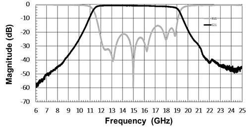
The filter exhibits good selectivity with an actual bandwidth (defined as fH - fL where fL is the low frequency -3 decibel (dB) cutoff and fH is the high frequency -3 dB cutoff) of 19.2 - 11.4 = 7.8 GHz—against a nominal Ku bandwidth of 18 -12 = 6 GHz. Of note is how rapidly the frequency response declines after the low and high-frequency cutoff until it reaches a low or high-side rejection point (-40 dB for the B148QF0S). A good selectivity figure is a gradient of 15 to 20 dB per decade. The Knowles DLI bandpass filter has a figure of around 15 dB per decade (Figure 2).
 Figure 2: Frequency response of the B148QF0S microstrip on ceramic bandpass filter. Designed for satcom Ku band operation, the device features a center frequency of 15 GHz and a bandwidth of 7.8 GHz. (Image source: Knowles DLI)
Future proofing
In time, even the Ku band will become congested. That’s why engineers have already started designing satcom systems for the K (18 to 26 GHz) and Ka bands (26 to 40 GHz). That means the SWaP demands that have driven bandpass filter development for Ku band phased antenna arrays will only increase. The good news is that prototype microstrip on ceramic bandpass filters have been shown to operate up to 70 GHz, and commercial devices that can handle up to 40 GHz are already available. This makes the products a suitable solution for not only today but also for tomorrow’s advanced satcom applications.
Conclusion
Knowles DLI’s work in high-K dielectric materials has resulted in high-Q bandpass filters that allow designers to meet the needs of the Ku band, with the added benefit of low power losses, improving efficiency, and helping with temperature stability. The breakthrough comes just as the Ku band is starting to get crowded, with work beginning for the shift to the K and Ka bands. As it happens, the new materials are well-suited to the higher frequencies, with prototypes operating up to 70 GHz.

Have questions or comments? Continue the conversation on TechForum, DigiKey's online community and technical resource.
Visit TechForum


