4D Systems Overview
Recently a project came up where there was a need for a training session timer. It was requested that a touchscreen display be utilized and be self-contained as well as capable of pairing with dongles for multiple users. This meant that the solution considered needed to support programming on the device, wireless control over dongles, and be capable of indicating session status on the display. It will include some supporting components like a real-time clock and mesh network transceiver that will not be addressed in this article.
Knowing the capabilities that are needed, there are many options that would fit the bill. Any number of microcontrollers could be used including Arduino and PIC based. Alternatively, a single board computer could be used such as a Raspberry PI. Either way, the controller would also need enough I/O to communicate with the display, real-time clock, micro SD card for information storage, and the selected mesh network transceiver. Coupled with the microcontroller is the need for a touchscreen display. The display would have to be large enough to provide room for the schedule, making the preferred size around seven inches.
Each of the options above would work in some fashion but would be limiting in one way or another. The smaller Arduino and PIC options have plenty of processing power to handle this type of project but would quickly run out of I/O. The Raspberry PI or similar single board computer would most likely be overkill for the application but offer some advantages over a basic microcontroller. Either way, all of these options run into the same difficulty which is graphic user interface (GUI) design. There are options to help in creation of GUI’s for both microcontrollers and single board computers, but none are as easy to use and intuitive as the product selected.
4D Systems’ Gen4-uLCD-70DCT-CLB (DigiKey part number 1613-1277-ND) coupled with 4D Systems’ Gen4-PA (DigiKey part number 1613-1210-ND) and 4D Workshop (DigiKey part number 1613-1393-ND) was the best solution for this project. The display is run by the Diablo16 processor which also offers a full set of I/O and can interface with SPI, I2C, serial, digital, and analog devices. On top of that, the display uses an on-board micro SD card for image storage which can be accessed for data storage in programming.

The project was started in the 4D Workshop. The first step was creating a new 4D Systems Project and selecting the correct display type. From there it’s a matter of selecting which environment to set up your display in. The options are Designer, ViSi, ViSi Genie, and Serial. For this project the display graphics were set up in ViSi Genie then the code was ported over to ViSi to have access to the 4DGL code.
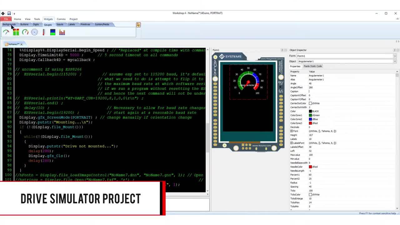
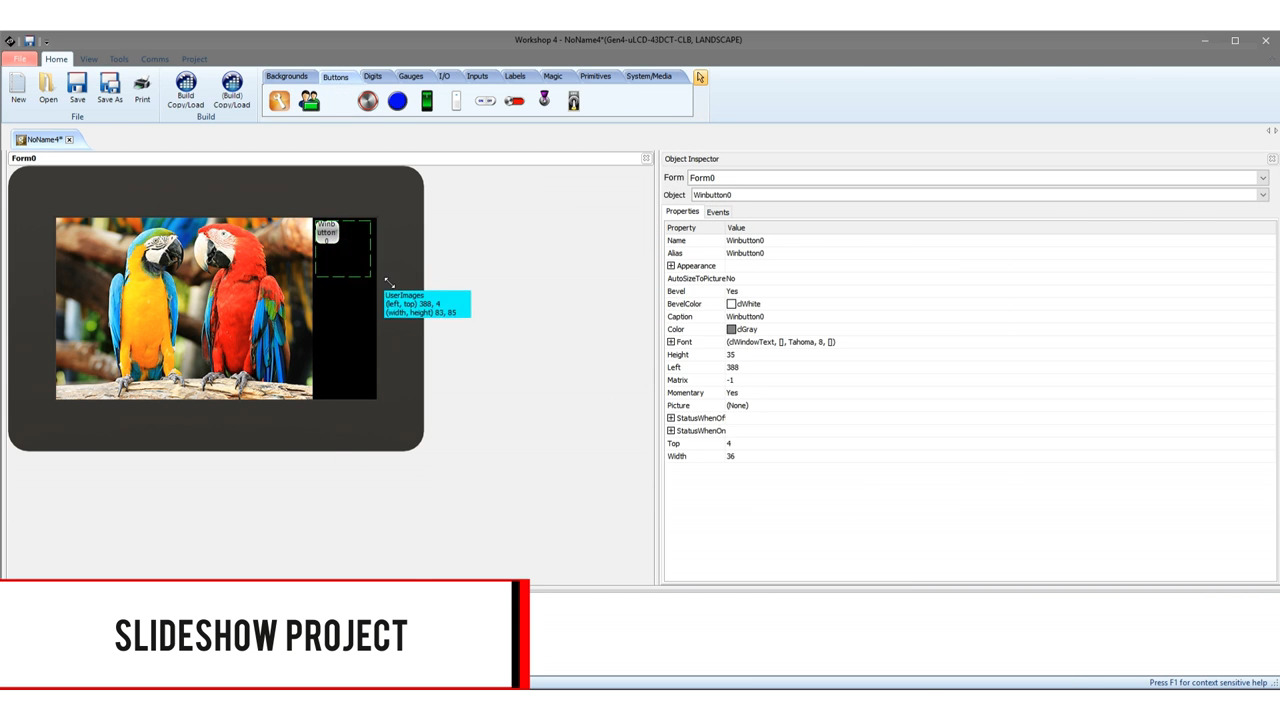
ViSi Genie allows for full graphic development in an easy and intuitive way. The software will start out with a single page or form. From here display backgrounds, buttons, digits, gauges, I/O, inputs, labels, magic, primitives, and system/media objects can be placed and integrated into the project. Once an object is selected and placed on the form it can be further edited by the object inspector. Objects can be renamed and have their properties edited from the default view in the object inspector. If simple commands from an object are required, like a button toggling an onscreen LED, this can be done on the second page of the object inspector called “events”. If there is a need for multiple forms they are easily added from the System/Media tool bar at the top of the designer. The project can be compiled and loaded to the display at any time from the top tool bar to check functionality. In testing, it is best to set your default destination to “Run RAM” to avoid wasting flash write cycles. This can be changed on the Project tab.
After all graphics were developed and all forms were set, the project was ported over to ViSi which gives a “what you see is what you get” representation of the display and the 4DGL IDE coding environment. This is where all the “heavier” coding was written using the Diablo16 internal functions. The I2C bus was set up for running the RTC for time and date retention. All I/O for communication with the mesh network transceiver was programmed in this environment, and there were multiple events that drive these pins. This specific project needed retention of a set of variables which were written to the on-board micro SD card located on the display to be retained through a power cycle. Also all comparative code to run the timer was programmed in this environment.
In conclusion, the 4D Systems software and displays are a powerful but easy to use option. The simple program interface and automatic code generation of ViSi Genie and ViSi make graphic development a quick process. The integrated Diablo16 processor gives a whole host of I/O and communication methods to either run code on board or interface with another device for more in-depth projects.
About this author

4D Systems, based in Australia, is a worldwide leader in the development and manufacture of intelligent graphic display modules. 4D Systems designs and manufactures compact and cost effective intelligent display modules and accessories using latest state of the art OLED and LCD technology. 4D Systems display modules feature embedded custom graphics processors that deliver stand-alone functionality to a multitude of application possibilities. 4D Systems products have successfully been implemented into the medical, aeronautical, military, and automotive sectors.

Have questions or comments? Continue the conversation on TechForum, DigiKey's online community and technical resource.
Visit TechForum