Utilizing the Latest Integrated Modules for Reliable Digital Power
Contributed By DigiKey's North American Editors
2016-11-30
The falling cost of components and software control has made digital power a popular solution to the problem of controlling multiple voltages across extremely complex designs. However, digital power has its own challenges, especially if it’s added to an existing design. In addition, digital control adds the need for firmware development, which analog designers have in the past tended to eschew.
This article will quickly outline the advantages of digital power control before defining two digital control approaches. The first is a “digital wrapper” approach that still relies upon analog voltage regulators. The second is a fully digital design solution. The article will then show how you can take advantage of the latest digital power IC features to engineer a stable power supply with faster transient response times, greater bandwidth and better overall performance.
Analog works fine: Why go digital?
Analog techniques have long dominated the design of switching DC/DC converters (voltage regulators) because they were relatively simple and inexpensive to implement. However, analog design has its downsides, notably the tricky business of control-loop compensation.
Digital design offers an alternative, particularly as the components required to support a digital power supply have dropped in price, dimensions and power consumption. Digital components allow designers to finely tune the control of their circuit such that transient response is enhanced and efficiency maximized.
In practice things can be a little more complex, particularly as one silicon vendor can have a different definition of “digital power” from another. Some suppliers define the technique as a power supply solution with a digital interface that takes advantage of the functionality offered by the Power Management Bus (PMBus) protocol coupled with an analog control loop in a “digital wrapper” solution. Other firms insist that digital power is a fully digital control loop powered by a microprocessor or digital signal processor (DSP).
Each technique brings its challenges: the digital wrapper still leaves you with the control-loop compensation challenge you were perhaps trying to eliminate in the first place, while a full digital solution carries the inherent implication that a designer might need to do a significant amount of coding to get the digital power system up and running. However, a new generation of digital power controllers and modules promises to address the challenges of both digital wrappers and full digital solutions.
Adding a digital wrapper
Adding digital power to an existing analog topology brings a number of advantages. Key among these is the bidirectional communication facilitated by the System Management Bus (SMBus) using the PMBus protocol.
PMBus is the standard protocol for communicating with power conversion systems using a digital communications bus. It builds on SMBus, because while SMBus was designed for communication with low-bandwidth devices, PMBus is targeted at digital management of power supplies, components, and power-related chips such as a rechargeable battery subsystem.
SMBus itself was based on Inter-Integrated Circuit (I²C), the serial, single-ended computer bus originally designed by Philips and used for attaching low-speed peripherals to a motherboard or other embedded system. As a result of this foundation, PMBus is a relatively low-speed, two-wire communications protocol. However, unlike SMBus and I²C, PMBus defines a substantial number of domain-specific commands rather than just detailing how to communicate using commands defined by the user.
In March of 2005, version 1.0 of the PMBus specification was published. More recently, a revised specification, version 1.3, was released. This version reduces latencies using higher-speed communications and also added a dedicated Adaptive Voltage Scaling (AVS) bus to statically and dynamically control processor voltages. The standard is owned by the System Management Interface Forum (SM-IF) and is royalty-free.
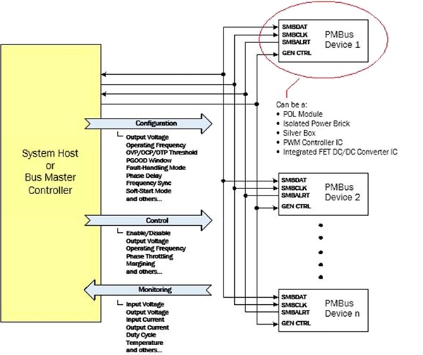
Using PMBus-enabled devices for power conversion provides flexibility and control that is not possible with traditional analog power systems. By designing with digital power, the adjustment of output voltages, power sequencing and synchronization of multiple voltage rails can be easily managed through a host controller via PMBus (Figure 1). (For more information about PMBus for digital power supplies see the library article, “Digital Voltage Regulator Control Using PMBus”.)

Figure 1: Bi-directional communication via SMBus using the PMBus protocol allows configuration, control and monitoring of multiple power-supply devices. (Source: Intersil)
Moreover, by using SMBus and PMBus, a new voltage rail can easily be added to a power management system. There is no need to reprogram or add more standalone power management ICs to facilitate the additional voltage rail, and the rail is easily integrated into the monitoring, sequencing, margining and fault-detection schemes.
Digitally configurable and controllable switching voltage regulators are widely available. For example, Microchip’s MIC24045 is a digitally programmable, 4.5 V to 19 V input range, 5 A synchronous step-down (“buck”) regulator for multiple voltage rail applications. Various parameters can be programmed via I2C such as output voltage, switching frequency, soft-start slope, margining, current limit values and startup delays. In addition, the MIC24045 supplies diagnostics and status information through the I2C interface.
While SMBus and PMBus bring the convenience and flexibility of digital configuration, control and monitoring to suitably interfaced analog power supplies, this digital wrapper solution falls short of full digital control, and hence fails to reap the full benefits of the approach. Each analog device attached to the bus operates according to its own control loop(s), which determine the device’s stability and frequency response, which in turn determines factors such as how quickly the power supply reacts to rapid changes in load. (See library article, “Understanding Switching Regulator Control Loop Response”.)
Frequently the designer is faced with the need to modify an analog power supply’s control loop to improve stability and frequency response through the addition of compensation networks. (See the library article, “Designing Compensator Networks to Improve Switching Regulator Frequency Response”.) This is a task that sends chills down the spine of many less experienced power supply designers. However, it is a task that can be avoided by moving to a full digital solution.
Maximize the benefits of full digital power
Full digital solutions are implemented by not only using digital configuration, control and monitoring enabled by the SMBus and PMBus protocol, but also by implementing digital control loops for the individual voltage regulators attached to the bus.
The principle of digital control is rather simplistic. In an analog regulator, the control loop is based on comparing the error between the actual output voltage and the desired output voltage. In a digital regulator, an analog-to-digital converter (ADC) translates that error voltage into a digital value. The precision of this translation is governed by the resolution of the ADC, but even with modest resolution, the result is likely to be more precise than that measured by an analog comparator. The higher the resolution of the ADC, the better the control of the voltage regulator.
In addition to the ADC, a proportional-integral-derivative (PID) processor is employed to replace the compensator network of the analog device. PID processors are clever devices used in many closed-loop control processes. The PID processor uses the digital error voltage reading to correct the voltage regulator’s output by constantly adjusting the duty cycle of the pulse train generated by the regulator’s digital pulse-width modulator (PWM) chip. The PID processor must also take on the job of compensating for gain and phase-shift factors around the control loop, just as the compensator network does in the analog version.
The digital PWM generates the same variable-width drive pulse as its analog counterpart, but it does so by “calculating” and then “timing” the desired duration of ON and OFF periods of the output signal that forms the square wave. In contrast, the analog PWM operates by triggering ON at a clock transition and triggering OFF when a fixed voltage “ramp” reaches a preset trip voltage.
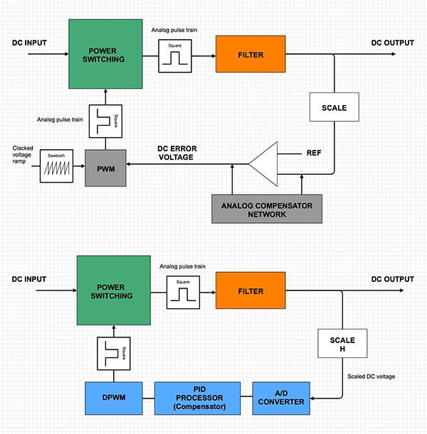
The precision of the reference voltage and the update frequency of the ADC output to the proportional-integral-derivative (PID) processor significantly enhance the stability and accuracy of the output voltage compared to analog voltage regulators. Figure 2 compares an analog switching regulator block diagram with that of a digital equivalent.
(For a more detailed description of digital power control, see the library article, “The Rise of Digital Control for DC/DC Regulation”.)

Figure 2: An analog switching voltage regulator (top) often requires a tricky-to-design compensator network to ensure the device is stable yet offers good bandwidth, phase margin and gain margin. In a digital equivalent (bottom) the job is done by a PID processor. (Diagram drawn using DigiKey Scheme-it®)
While the principle of digital control is simple to understand, implementing the technique is far from trivial, though recent advances are making it easier. The key to stability combined with good frequency response in order to respond rapidly to changes in load, largely comes down to the algorithms that determine how the PID processor commands the control loop.
Traditionally, digital control solutions demanded the services of general purpose microcontrollers or DSPs to perform the PID processing function. Unfortunately, since such devices were not specifically designed for power supplies, they demanded a lot of software coding and firmware design. Apart from extending project schedules and pushing up costs, this required coding talents that were beyond the skills of many analog power supply designers.
New digital power modules ease coding challenge
Today, several silicon vendors offer “digital power modules.” These are specialized devices that take advantage of both the flexibility offered by digital configuration, control and monitoring implemented by SMBus and the PMBus protocol, while also offering specialized digital control-loop commands. Such devices eliminate the compromises of general purpose microcontrollers and DSPs, and save time by shortening lengthy coding cycles.
Texas Instruments' UCD3138 Digital Power Controller is a good example of such a device. Key to the chip’s functionality is its digital control loop peripherals. Each of these peripherals implements a high speed digital control loop consisting of a dedicated error ADC (EADC), a PID-based two pole/two zero digital compensator, and digital PWM (DPWM) outputs with 250-ps pulse-width resolution. The device also contains a 12-bit, 267-ksps general purpose ADC with up to 14 channels, timers, interrupt control, PMBus and UART communications ports. The device is based on a 32-bit ARM® microcontroller that performs real-time monitoring, configures the peripherals and manages communications. Three sets of peripherals are available which operate autonomously to simultaneously command three independent control loops.
In order to maximize the operational efficiency of the digital power controller, it is necessary to set up the PID coefficients to suit the connected switching voltage regulators. Setting up the digital compensators is straightforward since TI limited assigning bit values to specific pre-defined registers. The UCD3138 controllers don’t require complex code development to continuously compute complex mathematical transfer functions.
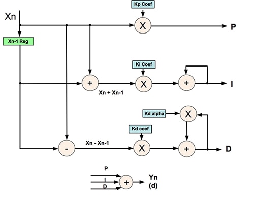
TI has produced an application report (see reference 2) which shows you how to use a network analyzer to produce a Bode plot of the initial voltage and current control loop of a power supply circuit. Changes can then be made to the PID coefficients (see Figure 3) until the two pole/two zero digital compensator gives the power supply the desired bandwidth, phase margin and gain margin. Once these coefficients are determined, they can be programmed into the UDC3138 controller, which will then ensure that the connected devices are always operating under optimum conditions.

Figure 3: UCD3138 controller PID structure. With the right input coefficients, the device ensures optimum operation of the attached switching voltage regulators. (Source: Texas Instruments)
Another example of a digital power module is the DM7803G Digital Power Controller from Bel Power Solutions. The DM7803G is a fully programmable digital power manager that uses the I2C communication bus interface to control, manage, program and monitor up to 32 point-of-load (POL) voltage regulators and four independent power devices. One key point for the designer is that the DM7803G eliminates the need for external components for power management, programming and monitoring of POL voltage regulators.
The device is programmed with the operating parameters of the connected devices via a graphical user interface (GUI). For each connected device it is possible to program the output voltage, voltage protection levels, optimal voltage positioning, turn-on and turn-off delays and slew rates, switching frequency and interleave (phase shift). Similar to the UCD3138 controller, once the PID compensation coefficients have been determined, the DM7803G also programs the feedback compensation loops of the attached POL voltage regulators.
While the products described above can be used as the basis for a full digital solution with little or no coding, a reasonable degree of knowledge about control loops and compensation networks is still an advantage in getting the most out of a digital power supply.
However, for developers who would rather accelerate the design process by eliminating as many external components as possible, a number of completely integrated digital power solutions are available.
These complete digital power solutions with integrating PWM control, power stage (MOSFETs), inductor and passive components together with a PMBus-enabled digital power controller, are available from several vendors. The application circuits for such devices are simple, comprised of the module itself and a few input and output capacitors.
The downside is the price: such devices are for prime high-end applications only, costing $30 to $50 apiece. Typical applications are to power ASIC, FPGA, DSP, CPU and memory chips for computing, communication infrastructure and industrial applications.
An example of such a digital power module is Intersil's ISL8271M. This voltage regulator module takes a 4.5 to 14 V input voltage and produces a 0.6 V to 5 V output at up to 33 A with an efficiency of 96 %. Intersil specifies that the device can respond to a transient load change within one clock cycle.
Figure 4 shows an application circuit for the device and illustrates its dimensions. The digital power module offers a high degree of programmability via its PMBus compliant I2C communication interface for parameters such as margining, current limit, soft-start and fault limits. The PMBus can also be used to monitor voltages, current, temperatures and fault status. As this is a fully integrated digital power supply, control-loop compensation has been set at the factory. The chip can be used as a standalone power supply or as part of a multi-regulator system where all chips are linked via the SMBus and PMBus protocol.

Figure 4: Intersil’s ISL8721M offers a highly-integrated digital power module which requires only the addition of a few passives for a complete digital power supply solution. (Source: Intersil)
Conclusion
There will likely always be a place for analog power supplies as they offer a simple, inexpensive and robust solution. Some knowledge of control loop compensation techniques is an advantage, but by basing the design on one of the many modular switching voltage converter products and following a manufacturer’s reference circuit, it is possible to come up with a decent working solution.
On the other hand, for more complex applications such as industrial computing, telecommunications and wireless communication systems which require multiple power lines and voltages, analog solutions quickly become inflexible and unwieldy. Digital control of applicable analog voltage regulators simplifies the design of such systems and eases the addition of voltage lines late in a product’s development cycle.
Full digital design whereby a digital supervisor not only configures, controls and monitors the bus-connected power supplies and looks after control-loop compensation, further eases power supply design for complex systems, albeit with increased cost.
That said, the price of digital power management components continues to drop. Moreover, the level of integration has risen to a point where fully integrated digital power modules that only require the addition of a few external capacitors to form a fully functional power supply are now commercially available. These trends are set to continue and will likely see digital technologies outpace their analog counterparts.
References:
- “The Benefits of Using Digital Power Modules,” Intersil, 2014.
- “UCD3138 PFC Tuning,” Bosheng Sun, Zhong Ye, Application Report SLUA709, Texas Instruments, March 2014.

Disclaimer: The opinions, beliefs, and viewpoints expressed by the various authors and/or forum participants on this website do not necessarily reflect the opinions, beliefs, and viewpoints of DigiKey or official policies of DigiKey.


