Use Transient Voltage Suppression Diodes to Ruggedize Circuits and Maintain Electrical Integrity
Contributed By DigiKey's North American Editors
2023-10-17
Electrical fast transient (EFT) voltages are a reality that designers must account for to protect their circuits, systems, and system users. EFTs have many sources, including common electrostatic discharge (ESD) due to an simple actions like walking across a rug, starting a motor, or striking lightning causing a ripple effect. These transients can adversely affect every product class, from low-voltage battery-powered wearables to high-power motor systems.
The effects of EFTs range from temporary disruption and inability to function to long-term degradation in performance and outright permanent damage and failure. While designers can take steps to reduce voltage transients, such as using anti-static enclosures, filtering, clamping at the source, or implementing additional grounding, these measures often need to be revised or upgraded depending on the specific application scenario.
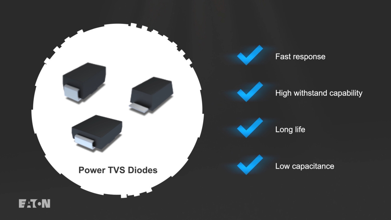
To reliably minimize or eliminate the detrimental consequences of transient voltages, designers can use two-terminal passive components called transient voltage suppression (TVS) diodes. Although generally viewed as an open circuit, these diodes react almost instantaneously and resemble a short circuit when the transient event occurs, thus diverting the transient overvoltage to ground. TVS diodes offer fast response, high voltage-withstand capability, long life, and low capacitance.
This article will examine the need, role, types, and application of TVS diodes, using various device families and devices from Eaton Corporation plc (Eaton) for examples.
Start with IEC standards
To mitigate the risks of EFTs, the International Electrotechnical Commission (IEC) has defined three internationally recognized standards for overvoltage protection within IEC 61000-4 (“Electromagnetic compatibility (EMC): Testing and measurement techniques”):
1) IEC 61000-4-2 covers system-level ESD immunity, which applies to ESD caused by human contact (Figure 1). For this waveform, the rise time (tr) is short at 0.7 to 1 nanosecond (ns), with most of the energy dissipating within the first 30 ns, after which it rapidly decays. Therefore, very fast-acting overvoltage protection is required for a timely response to ESD events.
 Figure 1: A typical ESD pulse waveform due to human contact, as characterized by IEC 61000-4-2, shows a very short rise time of less than a nanosecond, with most of the energy dissipating within the first 30 ns. (Image source: Eaton)
The waveform alone does not indicate the associated voltage levels. IEC 61000-4-2 specifies test voltages for system-level ESD immunity in various equipment for contact and air discharge (Figure 2).
|
Figure 2: The IEC 61000-4-2 levels for air and contact discharge further define the human-contact specifics. (Image source: Eaton)
The appropriate choice of a TVS diode will depend on the level of ESD protection required in an application. Note that all of Eaton’s TVS diodes offer Level 4 minimum performance when tested to IEC 61000-4-2. Other options are available with even higher ESD withstanding protection, providing up to 30 kilovolts (kV) for both air and contact discharging.
2) IEC 61000-4-5 covers immunity against electrical surges, such as those from lightning or from switching power systems. Unlike relatively low-power static electricity, lightning strikes can contain up to 1 gigajoule (GJ) of energy and deliver up to 120 kV of surge voltage. Lightning-induced transients can occur due to direct lightning on outdoor electrical circuits producing surge voltages, indirect lightning strikes inducing surge voltages in conductors, or lightning ground current flows. Note that TVS ESD suppressors are not intended to protect against direct lightning strikes, but suppressors are still needed as these strikes can send transients throughout electrical distribution systems for distances of 1 mile or more.
IEC 61000-4-5 defines a typical lightning voltage waveform (Figure 3).
 Figure 3: This is the lightning pulse waveform defined by IEC 61000-4-5 (IPP is peak current). (Image source: Eaton)
The IEC 61000-4-5 standard also specifies test voltage levels for surge immunity in classes of electrical/electronic equipment (Figure 4).
The levels are defined by the end application:
- Class 1: Partially protected environment
- Class 2: Electrical environment where cables are well-separated, even at short runs
- Class 3: Electrical environment where power and signal cables run parallel
- Class 4: Electrical environment having interconnections run as outdoor cables along with power cables, and the cables are used for both electronic and electric circuits
|
|||||||||||||||||||||
Figure 4: IEC 61000-4-5 defines four classes of test levels for electrical surge immunity. (Image source: Eaton)
3) IEC 61000-4-4 covers protection for EFTs (Figure 5). EFTs are caused by the operation of inductive loads, such as heavy-duty motors, relays, switching contactors in power distribution systems, and the switching in or out of power factor correction equipment.
 Figure 5: Shown is the EFT pulse waveform as characterized by IEC 61000-4-4. (Image source: Eaton)
Note that EFTs are often characterized simply by two paired numbers: their rise time to peak value (t1), and the pulse duration until the transient falls to 50% of peak value (t2). The 8/20 microsecond (µs) transient is a common pulse in industrial applications.
The magnitude of transient-voltage ESD a circuit or system must withstand depends on the application. Three classes are defined by MIL-STD-883, which is widely used by the industry, as well as military and aerospace systems (Figure 6).
|
Figure 6: There are three levels of ESD sensitivity classifications per MIL-STD-883 Method Number 3015. (Image source: Eaton)
TVS devices solve the problem
To meet various requirements and protect their systems, designers can use TVS diodes. TVS diodes are silicon overvoltage protection devices that work based on the diode avalanche-breakdown principle. They are installed parallel with the normal circuit to protect internal components from short-duration (transient) and medium/high voltages (Figure 7).
 Figure 7: The TVS diode is placed across the input, between the line being protected and the system ground. (Image source: Eaton)
In normal, non-transient operation, TVS diodes maintain a high impedance and do not interfere with power or signal transmission through equipment. However, when a TVS diode experiences an instantaneous, high-energy shock across its terminals, it protects downstream circuit elements by rapidly entering a low-impedance state (called avalanche breakdown) to absorb the large current and clamp the voltage to a safe level.
TVS diodes are available as unidirectional or bidirectional P-N junction devices. Despite the names, most unidirectional TVS diodes suppress voltages in both polarities. The difference is that unidirectional types have asymmetrical voltage-current (V-I) properties, while bidirectional TVS diodes have symmetrical V-I properties (Figure 8). Bidirectional TVS diodes are well-suited for protecting electrical nodes with signals that are bidirectional or both above and below the ground voltage.
 Figure 8: TVS diode names do not reflect any inherent directionality. Instead, unidirectional TVS diodes have asymmetrical voltage-current (V-I) properties, while bidirectional diodes have symmetrical V-I properties. (Image source: Eaton)
Top-tier parameters, packaging, and placement define TVS performance
TVS diodes are defined by many high-level specifications. Among them are:
- Nominal reverse working maximum voltage (VRWM): Also called reverse standoff voltage, this is the maximum operating voltage of a TVS diode when it is “OFF”
- Breakdown voltage (VBR): The voltage at which avalanche breakdown occurs in a TVS diode, resulting in low impedance
- Reverse leakage current (IR): The current that flows through a TVS diode when it is reverse-biased
- Clamping voltage (Vc): The voltage across a TVS diode at its peak pulse current (Ipp) rating
- Capacitance: A measure of stored charge, generally in picofarads (pF), between the input pin and another reference point (often ground/earth), typically measured with a 1 megahertz (MHz) signal
- Peak current (Ipp): The difference between a current waveform's maximum positive and maximum negative amplitudes
Selecting a TVS diode is typically a four-step process:
- Select a diode with a standoff voltage that is higher than the normal operating voltage
- Verify that the specified peak current exceeds the expected peak current and ensure that the diode is specified to handle the required power during a transient event
- Calculate the maximum clamping voltage (VCL) of the selected diode
- Confirm that the calculated VCL is less than the specified absolute maximum rating for the protected pin
TVS device placement on the circuit board is critical to realizing the full performance capabilities of these devices. For the best surge protection, the diodes should be placed as close as possible to the point of voltage entry, such as the I/O ports, to minimize the impact of parasitics on the effective suppression of the fast transient surges.
Example TVSs illustrate the range of offerings
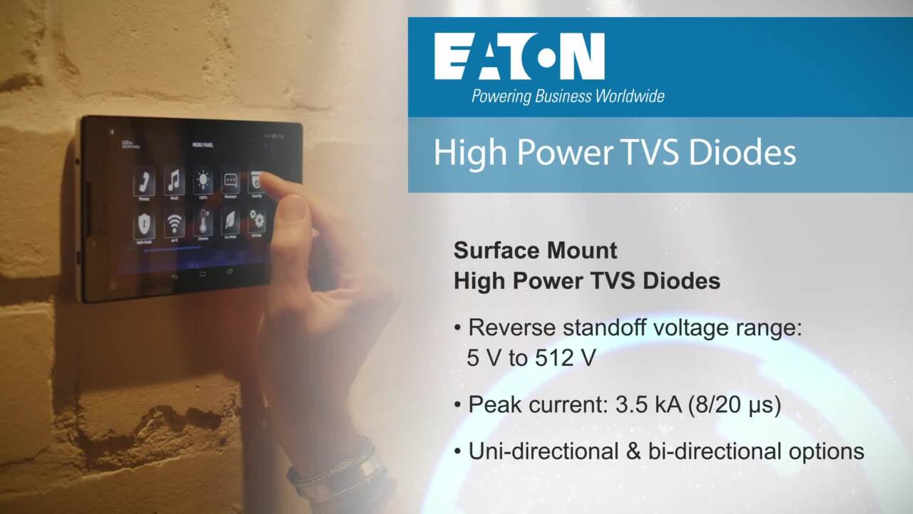
Eaton’s TVS diodes are well-suited to overvoltage protection in I/O interfaces and high-speed digital and analog signal lines. They offer very low clamping voltages, high peak power, high current dissipation, and nanosecond response times.
TVS diode packaging is closely related to the specifications. Both surface-mount and through-hole packages are available, with the latter offering higher voltage/current performance.
TVS diodes must protect against a wide range of voltages and currents. Therefore, one value of voltage rating and other parameters cannot satisfy all EFT situations. Examples from four distinct families illustrate these points.
1) The SMFE series has a peak pulse power capability of 200 watts with a 10/1000 µs waveform. The devices are housed in an industry-standard low-profile SOD-123FL surface-mount package measuring 2 × 3 × 1.35 millimeters (mm) that optimizes board space for mobile and wearable devices.
One member of the series is the SMFE5-0A (Figure 9). It has a 9.2 V clamping voltage, a 21.7 ampere (A) Ipp, and supports unidirectional or bidirectional use cases. Reverse leakage current is under 1 μA above 10 V operation, and the response time is fast, typically less than 1.0 picosecond (ps) from 0 volts to VBR.
 Figure 9: The SMFE5-0A 9.2 V TVS diode comes in a low-profile SOD-123FL surface-mount package and targets mobile and wearable applications. (Image source: Eaton)
2) The ST series protects one bidirectional I/O line, and targets USB and other data ports, touchpads, buttons, DC power, RJ-45 connectors, and RF antennas. Members of this family such as the 33 volt, 12 A Ipp STS321120B301 are housed in a tiny SOD-323 SMT package measuring 1.8 × 1.4 × 1.0 mm and are rated to 400 watts peak pulse power per line (tP = 8/20 μs). Diodes in this series support working voltages spanning 2.8 volts DC (VDC) to 70 VDC with ultra-low capacitance down to 0.15 pF. These diodes provide ESD protection up to 30 kV (per IEC 61000-4-2).
3) The AK series comprises high-power TVS diodes with up to 10,000 A protection and is designed to meet severe surge-test environments for AC and DC applications. These diodes feature low slope resistance as well as a superior clamping factor due to snapback technology. They meet UL1449 surge-protection device standards for applications such as consumer electronics, appliances, industrial automation, or AC line protection. (Note: slope or dynamic resistance is the resistance offered by the diode when an AC voltage is applied; snapback is a device process whereby conduction of large currents continues even at lower voltages.)
To meet the amperage and UL requirements, devices in this series use through-hole axial-lead packaging as used with the AK6E-066C, a 120 V clamp, and 6000 A Ipp diode (Figure 10). This diode measures 25 mm along its leads, with a nearly square “central” body that measures approximately 13 × 15 mm.
 Figure 10: The AK6E-066C high-power 120 V TVS diode offers up to 10,000 A protection and is housed in a through-hole axial-lead package. (Image source: Eaton)
4) The SMAJExxH series SMA-size TVS diodes are unique in that they are qualified to AEC-Q101 standards required for automotive applications. They provide 400 watt peak pulse power capability (with a 10/1000 μs waveform) and have a fast response time that is typically less than 1.0 ps from 0 V to VBR, along with IR less than under 1 μA above 10 volts.
Devices in this family span from 5 to 440 volts with unidirectional and bidirectional versions for each device and include the SMAJE22AH, which features a 35.5 V clamping voltage with 11.3 A Ipp (Figure 11). All devices in the series are housed in surface-mount plastic packages measuring 3.0 × 4.65 × 2.44 mm (maximum) and meeting the UL 94 V-0 flammability rating (Figure 11).
 Figure 11: The SMAJE22AH 35.5 V TVS diode is qualified to automotive standards as called out by AEC-Q101; it also uses plastic packaging that meets the UL 94 V-0 flammability rating standard. (Image source: Eaton)
Conclusion
Electrical transients from static electricity, motor startup, or nearby lightning can damage electronic systems and their components. TVS diodes respond to these overvoltages almost instantaneously and divert the transient voltage and energy to ground, thus protecting the system. As shown, Eaton offers various series of TVS diodes, each series comprising numerous devices rated at different voltages to match the anticipated transient-voltage magnitude, end-product constraints, and regulatory mandates while requiring only a few square millimeters of circuit-board real estate.
Disclaimer: The opinions, beliefs, and viewpoints expressed by the various authors and/or forum participants on this website do not necessarily reflect the opinions, beliefs, and viewpoints of DigiKey or official policies of DigiKey.