Use The Right ICs to Extend Wearable Device Battery Life
Contributed By DigiKey's North American Editors
2016-10-05
From fitness and health trackers and smart watches to virtual reality heads up displays, designers are constantly searching for new, innovative methods to reduce current consumption, reduce system activity and keep system functions in standby or sleep mode as much as possible. At the same time, they need to reduce power consumption while in standby mode by selecting devices with minimal leakage current or use load switches to disconnect subsystems when not needed.
Selecting the right battery charge management system plays a central role in this process. The latest generation of battery charge ICs helps designers achieve their power-conservation goals and maximize battery life by integrating key battery charge functions, supporting the use of a wide range of battery sizes and capacities, offering very low quiescent current and adding power-management functions that help extend light load efficiency down to lower current levels.
Complex charging cycle
While Li-ion batteries offer tremendous advantages over alternative battery chemistries including higher power density and lower self-discharge rate, they bring their own distinct set of liabilities. Li-ion batteries are highly sensitive to overcharging. Voltages exceeding a certain rate will stress the material and shorten the life of the battery. This limitation not only requires a more complex charging cycle; it can also present a safety risk if the battery is charged beyond 4.2 V per cell.
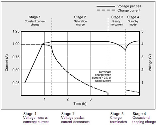
The ideal constant-current, constant-voltage (CCCV) charging profile used to charge Li-ion cells presents a fixed or constant current to the cell until the voltage reaches 4.2 V (Figure 1). In this stage the battery voltage increases in a near-linear fashion. When the voltage reaches 4.2 V, the system switches to constant voltage mode. In this stage the cell voltage is never allowed to exceed 4.2 V as the current slowly declines. When the cell reaches 4.2 V with no current applied, it is considered fully charged.

Figure 1: In practice, vendors tweak the pre-conditioning phase and add thermal regulation steps and time limits to the CCCV charging cycle to protect the battery. (Image source: batteryuniversity.com)
In practice, most chargers make some modifications to the ideal charging profile to protect the battery from potential fault conditions. For example, to avoid damage from charging a shorted or damaged cell, chargers begin the charging process by applying a small test charge rather than run at the full fast-charge rate. This allows the charger to wake up the battery and determine if the battery’s internal safety switch has been tripped. Typically, this pre-charge current is a small fraction (approximately 10 percent) of the normal fast-charge current.
Once cell voltage exceeds 3.0 V it is considered safe to charge at the maximum fast-charge rate. The charging process usually ends once the cell can hold 4.2 V with a pre-defined low current. However, the charger does not allow the current to taper down indefinitely. Instead the charge is terminated at the pre-defined current level and cell voltage drops to a slightly less than full-charge level of approximately 4.16 V to 4.17 V.
Charger ICs also include thermal regulation features to control overheating when the battery voltage is significantly lower than the input source. With this capability, the charger allows current and the fast-charge process to continue as long as the cell does not exceed a maximum temperature. Moreover, the entire charging process can be disabled based on sensors that monitor or estimate pack temperature.
Designers need a charging solution that charges the battery quickly; but they also need to store as much energy as possible in the battery. They can achieve this by using a charger IC that not only offers a termination current that is very accurate, but also one that can terminate reliably at 1 mA or below.
When should a wearable product designer use a linear or switch-mode charger? If the application calls for a low current, a small footprint and a relatively simple solution, linear chargers usually offer the better choice. Linear chargers generally offer a simpler solution that requires less application area, lower bill of materials (BOM) and fewer external components. For applications requiring current rates above approximately 1 A, switch-mode chargers offer higher efficiency and the ability to better manage thermal issues in compact wearable solutions. Moreover, for the most part, switchers deliver more features and better design flexibility.
The decision to use a host-controlled architecture offers additional options. In this case the system host processor manages the battery charging process while the charger performs all basic power conversion and monitoring functions. Designers basically trade off an additional investment in software development at the systems level for the ability to adjust charge voltage, current limits, timer settings and other parameters via software, gain more insight on fault conditions and more flexibility including the ability to adopt to different battery types.
Integrated solutions
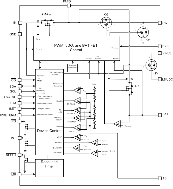
For designers trying to minimize power consumption, extend battery life and shrink product footprint at the same time, highly integrated battery charger solutions, like Texas Instruments’ bq25120, offer many of the key functions they need. The bq25120 integrates a linear charger, configurable LDO, load switch, buck converter, pushbutton control and a battery voltage monitor. To support long term, always-on functionality, the bq25120 delivers a quiescent current of just 700 nA with a buck converter operating at 1.8 V. The battery-management system also supports a wide range of batteries from 3.6 V to 4.65 V, and fast-charge currents from 5 mA to 300 mA. Designers can further minimize battery drain by using the configurable load switch/LDO to shut down infrequently used functions such as radios or displays. The bq25120’s standby quiescent current of 50 nA helps designers extend battery shelf life.

Figure 2: Besides integrating many of the key functions for wearable applications, Texas Instruments’ bq25120 battery management solution supports a wide range of batteries and charging profiles by offering programming from 5 mA to 300 mA. (Source: Texas Instruments)
A highly accurate termination charge can help maximize energy delivered to the battery. The bq25120 features a termination charge down to 500 µA to maximize energy delivered to the battery at the end of the charging cycle.
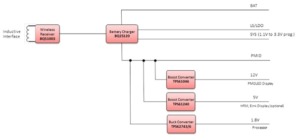
Over the last few years, designers of wearable solutions have increasingly turned to wireless charging schemes to power wearable solutions. The block diagram in Figure 3 depicts a design of a scalable power-management solution for wearable applications using a combination of Texas Instruments’ bq25120 charger and bq51003 integrated receiver. This circuit can be optimized for a wide variety of applications including activity monitors and watches. An I2C interface on the bq25120 facilitates communication and simplifies configuration of key parameters.

Figure 3: Combining the bq25120 charger (top center) with the bq51003 (upper left) wireless power receiver provides a scalable power management solution for wearable designs including monitors and watches. (Image source: Texas Instruments)
If designers need a second high-efficiency rail with a different voltage for an MCU, radio or sensor, discrete, low-power step-down converters like the TPS62743 offer performance similar to the bq25120, along with a choice of eight different user-selectable output voltages between 1.2 V and 3.3 V.
Circuit protection
Ensuring high reliability and safety is also a key consideration in the selection of any battery-charging solution for wearable applications. Diodes Incorporated has recently developed a simple solution that integrates a 1-cell lithium-ion battery protection chip with a dual N-channel MOSFET with a common drain. The resulting AP9211 Series delivers a variety of protection capabilities including overcharge (voltage/and/or current), over-discharge (voltage and/or current) and load short-circuit detection.
Constantly and accurately monitoring voltage and current, the AP9211 can rapidly disengage the MOSFET to protect against potentially damaging conditions. The use of a high-voltage CMOS process (30 V) allows the device to endure surge voltages. At the same time a built-in time delay helps protect external components and lower bill-of-materials costs.
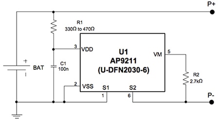
In a typical design using the AP9211, R1 and C1 are used to stabilize the supply voltage and R2 is connected between P- to VM sense terminal to monitor the status of charger and the charge/discharge current (Figure 4). R1 and R2 are also used as current-limit resistors if the battery or charger is connected in reverse.

Figure 4: The AP9211 from Diodes Incorporated offers a simple protection solution for single-cell Li-ion battery packs. A typical application circuit is depicted above. (Source: Diodes Incorporated)
The AP9211 also helps extend battery life by delivering a low quiescent current (3 µA normal, 0.1 µA in power down) that minimizes battery discharge. The device’s low-profile (< 0.6 mm) package offers wearable computing designers a slimmer protection circuit board design and allows them to support larger battery capacities for a given battery size.
Conclusion
As the wearable computing market continues to roll out and mature, we can expect ever-higher levels of functionality, so battery runtime will become an increasingly important differentiator. Selecting the optimal battery charging solution for a particular application will play a major role in the market success or failure of the on-coming wave of new wearable applications and designs.

Disclaimer: The opinions, beliefs, and viewpoints expressed by the various authors and/or forum participants on this website do not necessarily reflect the opinions, beliefs, and viewpoints of DigiKey or official policies of DigiKey.


