Use Specialized Inductors for High-Current, Fast-Transient DC/DC Converters
2025-07-08
Datacenters and server racks require kilowatts of power and hundreds of amperes of current. Providing this amount of DC power is a design challenge, even at low voltages. The problem is exacerbated by the need for microsecond transient response times to prevent more than a few millivolts of voltage-rail droop, which could cause intermittent circuit behavior.
To enhance response to transient demands, designers have transitioned to a multiphase DC/DC converter topology where multiple single-phase buck converters are used in parallel. However, this approach has inherent limitations due to the unavoidable parasitic inductance and resistance of the output capacitors, both of which slow the converter's transient response.
To overcome this weakness, an advanced multiphase topology known as the trans-inductor voltage regulator (TLVR) has been developed. Key to a successful TLVR implementation are two low-value, high-current inductors, one for each TLVR power phase, and a single compensation inductor on the primary side of the TLVR inductors.
This article examines the challenges associated with high-current DC/DC converters and explores the application of multiphase DC/DC topologies to address these challenges. It then describes the critical role of compensation inductors and how the performance requirements of these circuit elements can be met using example components from Abracon.
From single-phase to multiphase topologies
There are two related challenges in delivering regulated power to systems such as datacenters and server racks. First, they require hundreds of amperes of current. This static maximum current demand can be satisfied with a suitable switching converter design using high-value bulk capacitors to smooth out the switching ripple.
The second challenge is the dynamic one due to load transients, as loads quickly increase from a no-load or low-load idle state, necessary to reduce power use and minimize thermal issues, to their fully active state. The converter must respond within microseconds, yet without overshooting or undershooting the nominal rail voltage.
While bridging these contradictions is challenging, power supply and converter designers have devised ways to do so.
Begin with the single-phase converter
The standard step-down (buck) switching-topology DC/DC converter uses a single-phase approach (Figure 1, left). It takes an input DC rail, chops it into a high-frequency, square-like AC wave, and then downconverts this using a transformer or other arrangement. The resultant nearly pure DC is filtered via bulk capacitors to minimize ripple and provide a current boost if the load suddenly demands more current. To regulate the output to the desired voltage as the load varies, the converter uses feedback to adjust the chopped signal’s pulse width and duty cycle (Figure 1, right), ensuring its average value matches the target value.
 Figure 1: For regulation, the single-phase converter (left) modulates the on/off duty cycle of the switched pulse width (right) to maintain a stable DC output despite variations in load current. (Image source: Abracon)
However, this single-phase design has deficiencies in its transient response. The unavoidable parasitics of the capacitor’s effective series resistance (ESR) and effective series inductance (ESL) slow down its response time as it attempts to supply the required current when the load transitions from sleep mode to maximum demand.
Further, the additional current that is directed to the capacitor as the delivered voltage starts to sag must go through the converter’s inductor. While a larger-value inductor is preferable for certain aspects of converter performance, it also results in a slower rate of current change. Therefore, it will take the inductor longer to reach the current value needed to recharge the capacitor and meet the load requirement. Thus, inductor sizing is one of the many tradeoffs in converter design.
Then go multiphase
An ingenious topology that overcomes the limitations of the single-phase converter is the multiphase converter, which uses multiple single-phase buck converters operating in parallel. This provides designers with the flexibility to simultaneously use several smaller inductors to drive the load, rather than relying on a single large inductor.
The current to the load is the sum of the currents from all the phases (Figure 2, left). Since the inductance in each phase is lower than in a single-phase design, the current rises more quickly. This yields a faster response and lower voltage droop during load transients (Figure 2, right).
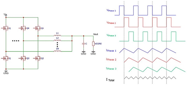 Figure 2: By employing multiple phases in a parallel arrangement (left) and summing their individual outputs, the transient response of the multiphase converter is much faster with lower droop (right) than it is for the single-phase topology. (Image source: Abracon)
Typical design practice is to limit a single phase to between 30 and 40 amperes (A), although it can be higher. A multiphase design typically consists of between two and eight phases, although more phases are possible. The choice between fewer, more powerful phases versus a higher number of less powerful ones involves many trade-offs among various aspects of electrical performance, physical size, bill of materials (BOM), and cost.
Improve multiphase with TLVR
The multiphase circuit output requires time to adjust the phases as they are sequentially triggered. In a clever circuit enhancement, the converter’s reaction time can be reduced by controlling how each phase is triggered in response to load transients. This is done using the TLVR approach.
This multiphase DC/DC converter topology provides a faster transient response by adding a series connection of secondary windings via inductors that couple all phases together. This, in turn, allows a simultaneous induction of current across the phases in response to an increase in load (Figure 3).
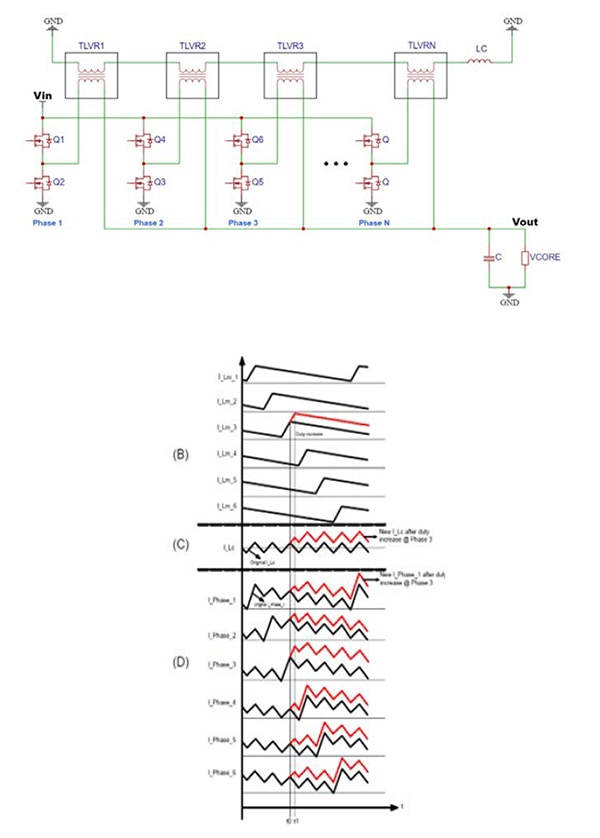 Figure 3: The TLVR topology adds interphase inductors (top) to couple the phases and enable them to have earlier “knowledge” of current demand (bottom). (Image source: Abracon)
Essential to the TLVR topology are the TLVR inductors and the compensation inductor. The former are specialized transformers where the primary and secondary windings comprise two copper clips to minimize DC losses (Figure 4). Both clips are contained within a magnetic core made of ferrite or iron-based material, thus magnetically coupling the primary and secondary sides. The key difference between the TLVR design and the basic multiphase configuration is the use of the primary winding of each TLVR inductor as an output inductor for every phase.
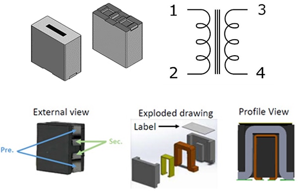 Figure 4: The TLVR inductor is a specialized transformer that links each phase’s output to the next phase. (Image source: Abracon)
In addition, the secondaries of all phases are interconnected in series to a single compensation inductor (LC) (Figure 3, top right). Each primary winding voltage is reflected on the corresponding secondary winding. Since all secondaries are connected in series, the compensation inductor sees the sum of all these waveforms.
In operation, when more current is drawn from the converter, the voltage at the output begins to drop due to the parasitic ESR and ESL of the capacitor. The feedback control loop senses this drop and responds by increasing the drive level of whichever phase is active at that time, sourcing more current through that phase to limit the voltage drop and meet the new load demand.
This is why TLVRs provide superior performance compared to traditional multiphase converters. When a given phase demands more current, this new current waveform is reflected across all primary windings since the secondary is coupled with all other phases. The result is a nearly instantaneous increase in current across all phases, due to the response of one phase to the feedback system, which induces a current through the other phases.
The “trans-inductor” in the TLVR name is due to this cross-phase inductor-linked approach. The collective response of all phases to changes in load bypasses the time interval that the controller needs to trigger each of the other phases, leading to a faster transient response.
TLVR inductors typically have a 1:1 turn ratio, with both inductance values the same. The inductance value is primarily a function of the duty cycle and the acceptable amount of ripple current.
Inductor design is key to TLVR performance
Passive components, such as resistors, capacitors, and inductors, are often looked upon as simple devices. While they are conceptually straightforward, the reality is complicated with many subtleties. The inductor is perhaps the most deceptive, as, in principle, it is “merely” a piece of bent or wound wire or conductor.
As noted, a TLVR inductor (Lmn) is needed in TLVR topologies for each power phase (Figure 5, bottom), allowing the system-level current supply to exceed hundreds of amperes.
In contrast, on the primary side of the TLVR topology, only a single compensation inductor (Lc1) (Figure 5, top) is required to regulate the supply. It achieves this by smoothing and adjusting the phase relative to the voltage, thereby increasing the phase margin and ensuring stable operation.
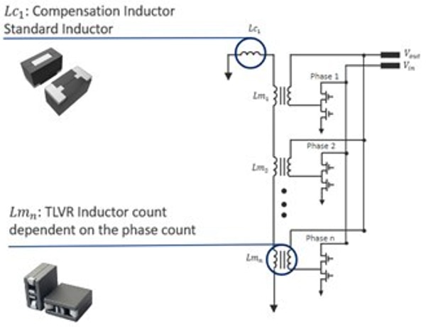 Figure 5: A complete TLVR multiphase converter requires one TLVR inductor per phase for interphase linking, plus a single compensation inductor to support stable operation. (Image source: Abracon)
AVR series assembly inductors
The compensation inductor used in TLVR designs must have low DC resistance, handle high currents, be specified over a wide temperature range, and be physically small. Abracon’s AVR series of assembly inductors (Figure 6) meets these requirements with its ferrite-based construction, inductance range of 22 nanohenries (nH) to 680 nH, operating temperature range of -40°C to +125°C, DC resistance (DCR) as low as 0.100 milliohms (mΩ), and saturation currents up to 160 A.
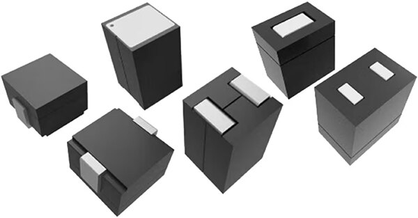 Figure 6: The AVR series of assembly inductors is specially designed, with construction, range of key parameter values, size, and more, to meet the unique needs of traditional DC/DC converters and for compensation in TLVR topologies. (Image source: Abracon)
The compensation inductor packaging also contributes to the success of a compact converter design. While molded inductors were previously standard for compact converter applications, these assembly inductors offer improved performance at a lower cost.
For example, the AVR-1F070605S90NLT is a shielded 90 ±15% nH inductor (0.1 MHz/1.0 V) measuring approximately 6 mm × 7 mm. Its DCR is 0.17 ±30% mΩ, and its typical saturation current is 50 A at +25°C, dropping only slightly to 45 A at +100°C.
For higher-current applications, the AVR-1Z090610SR12KT is an unshielded 120 ±10% nH inductor (800 kHz and 0.8 V). This 9.5 mm × 10 mm component features a typical DCR of 0.10 mΩ (maximum of 0.12 mΩ) along with a saturation current of 90 A at +25°C and 75 A at +100°C.
Conclusion
Transitioning from a single-phase DC/DC converter to a multiphase approach and then to a TLVR topology yields superior performance in applications where load currents are high and fast, requiring a crisp transient response and high output accuracy. Enhancing a multiphase design with the addition of a TLVR inductor for each phase, as well as with a single compensation inductor, enables this approach to meet design objectives. For the necessary compensation inductor, Abracon's AVR series of assembly inductors offers advanced and cost-effective solutions for multiphase voltage regulation.
Disclaimer: The opinions, beliefs, and viewpoints expressed by the various authors and/or forum participants on this website do not necessarily reflect the opinions, beliefs, and viewpoints of DigiKey or official policies of DigiKey.


