Use Shielded Connectors to Achieve Reliable High-Speed Connectivity in Dense, Compact Form Factors
Contributed By DigiKey's North American Editors
2023-09-07
Electrical shielding is a design and manufacturing consideration that has been on the engineer’s list of concerns since the earliest days of electronics, but it is increasingly worrisome as data rates increase and systems become smaller and more tightly integrated with more signal lines in closer proximity. These trends greatly complicate what is an otherwise simple concept: prevent external unwanted signals from reaching and affecting a conductor carrying a signal, and prevent the energy of a desired signal from radiating outward and affecting nearby conductors and circuitry.
To be effective, shielding must totally surround the active conductors, forming a 360° conductive barrier along the entire path, including the termination connectors. To achieve this, many designers assume they must use coaxial cables and connectors, as the internal cable shield can be terminated while retaining the 360° shield integrity. However, the resultant areal channel density when using coaxial cables is low, and so this approach is not suitable to meet the high-speed, high-density electrical and physical requirements of many board-to-board and board-to-backplane interconnect applications. The solution is to opt for high-speed, fully shielded interconnects. These support high signal-path counts in a single, fully shielded connector housing.
This article briefly discusses shielding basics and the challenges designers face when implementing high-channel-count interconnects and shielding where multiple single-channel coaxial cables would have excess aggregate size and bulk. It shows why all-encompassing 360° shielding is especially critical, and uses several families of shielded connectors from Samtec to illustrate design and implementation best practices for high-speed signal integrity in confined spaces.
Begin with shielding basics
Cables and their interconnects (connectors) are an essential part of nearly all systems. They may connect a motherboard to a mezzanine board, a board to a user panel, a specialized interface, or an input/output (I/O) arrangement. To maintain signal integrity, the interconnect must support the bandwidth of the signal(s) and also be resistant to electromagnetic interference/radio frequency interference (EMI/RFI). At the same time, it must also not allow radiation of EMI/RFI to adjacent interconnects, boards, or components, especially those conveying low-level or sensitive signals.
Shielding attenuates the impact of electromagnetic interference and radio-frequency interference. Depending on where and how it is placed, it may primarily attenuate the noise close to its source (sometimes termed the noise “aggressor”), or block it from reaching noise-sensitive circuitry (the “victim”) (Figure 1).
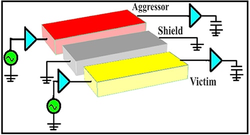 Figure 1: Shielding functions as a barrier between an aggressor source and an unintended, innocent victim of its EMI and RFI. (Image source: Journal of Computer Science and Engineering via Arvix)
Note that a given conductor may be both an aggressor emitting one “cluster” of EMI/RFI energy and also the victim of energy from another source. Further, the EMI/RFI aggressor does not have to be some external “third-party” source unrelated to the product; it can just as easily be another part of the system acting as an inadvertent aggressor by radiating energy onto an adjacent conductor or component.
There are many guidelines and so-called “rules of thumb” around how and where to terminate the ground shield of these cables and interconnects to block or significantly attenuate the transfer of noise energy between aggressor and victim. Unfortunately, not only are these guidelines often in conflict, but the right or best answer often seems to depend on the specifics of the arrangement. Among the suggested guidelines are:
- Terminate (ground) both ends of the shield.
- Terminate one end only, at the source.
- Terminate one end only, at the receiver.
Intuitively, it seems they can’t all be right, or maybe they can, depending on the specifics of the design and how much attenuation is needed. Comprehensive lab tests have shown that for effective shielding into the gigahertz (GHz) range, both ends of the shield must be terminated; in other words, the shield must be continuous and uninterrupted.
The rules are somewhat more flexible at audio and lower RF frequencies. However, termination of the shield at only one end may be acceptable for applications up to around 1 megahertz (MHz), but it is not suitable for 10s of MHz and above.
Full shielding is needed
Detailed test results also showed how the widely used short “pigtail” termination for the shield was often ineffective (Figure 2). Even if only a few millimeters (mm) long, its low inductance hurt its performance at higher frequencies and so could negate much of the shield’s performance. Worse, the innocuous pigtail terminal could actually be counterproductive by acting as a radiator of electromagnetic energy (an antenna), radiating more EMI/RFI rather than merely being ineffective at attenuating it.
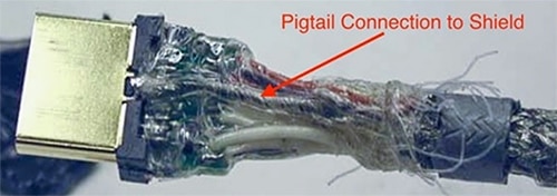 Figure 2: The innocuous-looking pigtail-style shield termination on this HDMI cable is not only ineffective but can be a counterproductive electromagnetic radiator. (Image source: Dana Bergey and Nathan Altland, via Interference Technology)
Instead, what is needed is 360° physical coverage at the shield termination, which is what is called for in most high-performance and MIL standards (Figure 3).
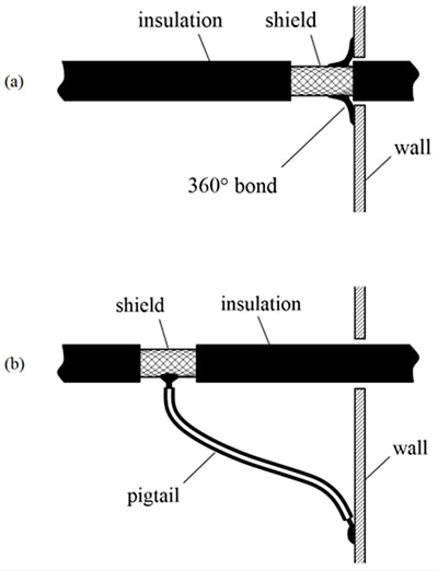 Figure 3: A full 360° termination (top) is needed for maximum shield effectiveness, rather than the quick-and-easy pigtail ground connection (bottom). (Image source: ResearchGate)
The need for termination at both ends with non-gapped 360° coverage is due to physics: as operating frequencies increase into the hundreds of MHz and GHz range, the corresponding wavelengths get shorter. This means that even tiny gaps in shield coverage represent a literal window of opportunity for signal energy to pass through with little or no attenuation.
Along with higher frequencies, today’s systems are densely packed. That means that any RF propagation path loss between the aggressor and victim is far less, as path loss increases as the square of the distance. Thus, even a seemingly insignificant amount of unintentional aggressor signal may reach and affect victim circuitry at a relatively high strength.
The use of a shield with 360° of integrity, often typified by individual coaxial cables and connectors, is certainly effective with respect to EMI/RFI protection. However, use of coaxial cable often interferes with the high physical density needs of many systems.
Further, many high-performance systems need shielding across multiple parallel signal lines, as seen in two basic scenarios:
• For board-to-board interconnects, such as between a motherboard and a mezzanine board, with a single shield around the multiple lines
• Multiple shielded coaxial cables in a single cable assembly, with a single mating connector
Single shield for board-to-board designs
The concept of using a single shield for multiple signal lines is straightforward in principle. The multiple lines are encased by a shield folded over the ferrule, making contact with the connector shell (Figure 4).
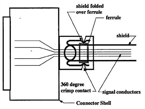 Figure 4: By wrapping the shield around the group of signal conductors, the multiple lines are shielded as a group. (Image source: Samtec)
This approach solves the shielding problem and requires minimal additional board space compared to an unshielded interconnect. It is important that the shielded multiline connector provides the same basic signal-line performance as an unshielded connector, while also ensuring reliable and consistent mating and unmating without compromising the shield.
An example of this multiline shielded interconnect is a 20-position board-to-board shielded connector pair, Samtec’s ERM8-010-9.0-L-DV-EGPS-K-TR header and the ERF8-010-7.0-S-DV-EGPS-K-TR socket (Figure 5). These rugged high-speed connector strips are designed for high-speed (non-return to zero (NRZ) encoding at 28 gigabits per second (Gbits/s) and four-level pulse amplitude modulation (PAM4) at 56 Gbits/s), high-cycle applications.
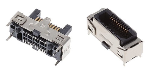 Figure 5: The 20-position ERM8 header (left) and corresponding ERF8 socket (right) provide shielded board-to-board connectivity. (Image source: Samtec)
The connectors provide up to 1.5 mm contact wipe and feature rugged latching, locking, 360° shielding, and are robust when "zippered" (pulled with an off-axis, non-normal force) during unmating. The high-speed performance is enabled by Samtec's Edge Rate contact system, which is designed for high-speed, high-cycle applications. It is optimized for signal integrity through a reduction in broadside coupling, and it has a smooth, broad-milled contact surface for decreased wear (Figure 6).
 Figure 6: To reduce broadside signal coupling, the ERM8 and ERF8 use a proprietary Edge Rate contact system. (Image source: Samtec)
The broad-milled contacts create a smooth mating surface area, unlike a stamped contact that mates on a cut edge. This smooth mating surface reduces the wear tracks on the contact, increasing the durability and cycle life of the contact system. It also lowers insertion and withdrawal forces.
Coaxial cables are also needed
Coaxial cables have an essential and irreplaceable role in signal transmission, but using interconnects that only support a single coaxial cable can be frustrating when multiple parallel signals are needed. To address this situation, Samtec offers a family of multiline shielded coaxial cable connectors that support 20, 30, 40, and 50 positions. Among these is the LSHM-110-02.5-L-DV-A-S-K-TR, a 20-position, self-mating, hermaphroditic surface-mount connector (Figure 7).
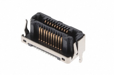 Figure 7: The LSHM-110-02.5-L-DV-A-S-K-TR is a 20-position, self-mating, hermaphroditic surface-mount connector with up to 50 positions. (Image source: Samtec)
The LSHM is a high-density, rugged connector for use in board-to-board and board-to-cable applications, with optional shielding for EMI protection. With its Razor Beam fine-pitch contact system, the hermaphroditic design saves printed circuit board (pc board) real estate in the X, Y, and Z axes. This connector features a 0.50 mm pitch and provides an audible click when mated, with mating and unmating forces approximately four to six times greater than typical micro-pitch connectors.
This board-mount connector is only half of the interconnect story, as a cable assembly is needed (Figure 8). This assembly also uses Razor Beam technology with a pitch of 0.50 mm.
 Figure 8: The Razor Beam fine-pitch self-mating coax cable assemblies provide a complete multiline board-to-cable solution. (Image source: Samtec)
A complementary cable assembly for the cited 20-position, board-mount, shielded multiline coaxial connector is the HLCD-10-40.00-TD-TH-1, a one-meter-long cable with self-mating, non-gendered, hermaphroditic connectors at each end (Figure 9). It uses 38 AWG micro-coax with a 50-ohm (Ω) impedance and is rated to 14 Gbits/s per contact.
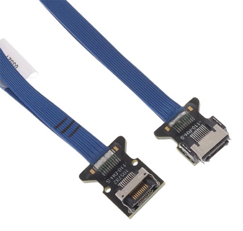 Figure 9: Multiline 50 Ω micro-coaxial cable assemblies such as the 20-position HLCD-10-40.00-TD-TH-1 include self-mating, non-gendered, hermaphroditic connectors at each end. (Image source: Samtec)
Putting it together
To make these high-speed connectors easier to specify and use, Samtec has extended the concept of manufacturer pc board layouts and connector SPICE models by offering reference designs for one of the most difficult design issues on the board: the critical “break out region” (BOR) around the high-speed connector. Samtec’s signal-integrity engineers have developed what they call a Final Inch Break Out Region with recommendations related to pc board trace routing for many of its high-speed connector series.
These design recommendations are based on use with standard board materials, multiple layers, and low-cost, high-yield manufacturing processes, and require no special treatment. These recommendations can save design, development, validation time and resources, and balance performance with manufacturability and cost.
Conclusion
Complete electrical shielding of cables, connectors, and interconnects is critical to signal integrity and performance for both board-to-board and board-to-cable configurations. The shielding problem is more challenging when there are multiple parallel signals that must be shielded to prevent EMI/RFI emissions or susceptibility to these emissions. As shown, Samtec offers various families of multiline board-to-board and coaxial cable-to-board interconnects to simplify design-in and manufacturing, while maintaining a high level of mechanical and electrical integrity and performance.

Disclaimer: The opinions, beliefs, and viewpoints expressed by the various authors and/or forum participants on this website do not necessarily reflect the opinions, beliefs, and viewpoints of DigiKey or official policies of DigiKey.


