Use a Contact-Cooled AC/DC Power Converter for Harsh Applications
Contributed By DigiKey's North American Editors
2025-03-04
As electronic devices proliferate, designers of power devices and AC/DC converter modules for harsh environments face increasingly challenging performance, environmental, and packaging requirements. While the role of a line-connected power converter module has not fundamentally changed, more is required to make it fully functional in the field.
First is the cooling issue because even an efficient supply gives off heat. Then, the designer must consider electrical and form-factor requirements at the system level. Finally, the converter must incorporate capabilities that simplify design-in and protect the converter, user, and load from adverse occurrences.
This article briefly examines the challenges facing designers of power systems intended for harsh environments. It then introduces a family of 504 W, contact-conduction cooled AC/DC converters from Advanced Energy and shows how they can address these challenges.
Begin with the cooling challenge
With very few exceptions, designers who incorporate an AC/DC converter into a system must also determine how to dissipate the heat generated. Even though modern converters are relatively efficient, typically 80% to 90% or higher, heat is still created and must be removed to ensure the supply does not overheat, thus compromising performance and reliability.
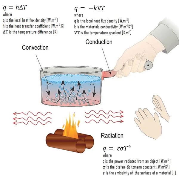
Thermal physics shows there are three ways to dissipate this heat (Figure 1):
- Conduction, by direct contact of a solid surface to a solid surface
- Convection, by a moving fluid, which can be air or liquid
- Radiation, as electromagnetic (primarily infrared) energy, which can occur in a vacuum
 Figure 1: Thermal energy can be dissipated by conduction, convection, or radiation. (Image source: Nuclear Power)
Radiation-based cooling is generally inadequate for electronic systems, as it transfers only a relatively small amount of heat. However, radiation is critical for spacecraft that must diffuse their heat into the vacuum of space.
Most designers prefer to begin their cooling strategy using convection of unforced (natural) or fan-forced airflow, with the air going through openings and vents in the converter unit. This method of cooling is relatively inexpensive and easy to assess.
However, the convection-cooling approach is not viable in many real-world installations. The converter must be inside the application’s sealed ingress protection (IP) rated casing for complete protection against water, rain, dust, and other contaminants. Further, most standard converters are not physically arranged or packaged for conduction-based cooling.
A different design is needed when the cooling must be achieved solely by thermal conduction from the converter’s enclosure to an adjoining surface. This is often called contact or cold-wall cooling. The packaging design of Advanced Energy’s Artesyn AIF500 power converter family (Figure 2) is a good example of this approach.
 Figure 2: The Artesyn AIF500 power converters use contact or cold-wall cooling. (Image source: Advanced Energy)
These low-profile units are mounted on a printed circuit (PC) board. They have an industry-standard full-brick baseplate footprint of 4.6 × 2.4 inches (in.), a height of 0.55 in (116.84 × 60.96 × 13.95 millimeters (mm)), and a weight of 9.2 ounces (oz) (260 grams (g)).
They are designed primarily for the remote radio-head RF power-supply requirements of 5G telecommunication applications. They are also suitable for displays and industrial applications. Their mean time between failure (MTBF) is over one million hours.
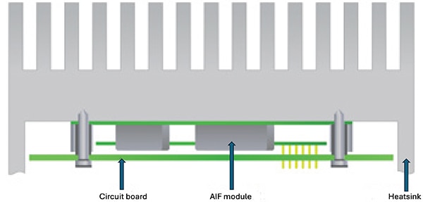
The modules are designed to be contact-cooled via their baseplate (Figure 3) and can deliver their full power rating over a wide baseplate temperature range of -40°C to +100°C.
 Figure 3: The AIF500 modules are designed for conduction cooling via their baseplate placed in direct contact with a colder surface. (Image source: Advanced Energy)
Selecting a power converter
The selection of any power converter starts with its core performance requirements. These include its ability to deliver a consistent output voltage to the load despite steady-state variations in line voltage, voltage transients, load demand changes, and ambient temperature shifts.
The fully encapsulated AIF500 units operate from 90 VAC to 264 VAC. Options include the AIF42BAC-01N with its fixed 12 V/42 A output or the 48 V/10.5 A AIF11WAC-01N. Start-up time to full output, an important parameter in many applications, is 3.5 seconds (s), while line regulation is ±0.2% and load regulation is ±4%.
Along with a wide-ranging AC line input and well-regulated DC output, the AIF500 converters also incorporate protection features such as undervoltage lockout (UVLO), overvoltage protection (OVP), and overcurrent protection (OCP). Internal inrush current limiting minimizes the external circuitry needed to prevent damage from start-up current surges.
Additionally, the converters are approved to meet relevant EN, UL, Canada UL, IEC, and EN 62368-1 safety standards and carry CE and UKCA safety marks. They achieve these certifications partly due to their multiple isolation ratings of 4,000 VDC input-to-output, 2,500 VDC input-to-baseplate, and 100 VDC output-to-baseplate.
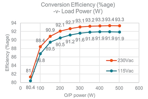
Regulatory requirements and good engineering practice require minimization of thermal load to obtain high-efficiency operation. These converters offer efficiency above 90% when operating at half-rated output power or higher. For example, the 12 V unit operating from a 230 VAC line has an efficiency greater than 93% at an output power of 300 W or higher (Figure 4). Above 300 W, the power factor (PF) exceeds 0.99, surpassing regulatory mandates.
 Figure 4: The AIF500’s power-conversion efficiency is greater than 90% when operating above the mid-load rating, which reduces thermal dissipation and meets regulatory requirements. (Image source: Advanced Energy)
Adding system-level features and functions
Today’s converters must offer capabilities beyond two wires for AC input, two wires for DC output, and two remote-sensing leads. They must also integrate at the system level with additional connections and functions.
For example, the AIF500 converters have a direct single-line “unit good” output and a TTL-level input for remote enable. When not enabled, their standby power is 5 W. These reporting and control signals are just a starting point for connectivity, as the converters also include a PMBus interface.
Additional features include the always-on fixed-voltage auxiliary output of 8 VDC to 11 VDC at 250 mA, which supports small, critical loads.
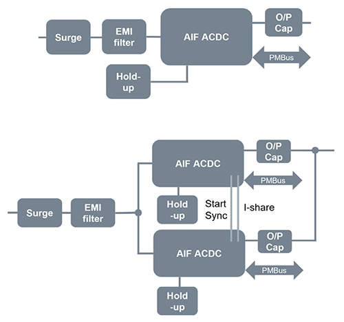
A single-unit converter configuration requires only an external electromagnetic interference (EMI) filter, a hold-up capacitor, and an output capacitor.
For applications where the output current of a single AIF500 unit is insufficient, the units support active current sharing, which extends the single-unit configuration to a maximum of ten units with simple unit-to-unit interconnects (Figure 5). This parallel-output arrangement requires only the addition of hold-up and output capacitors for the second unit (and each additional unit); no other components are needed.
 Figure 5: A single AIF500 unit requires only a few external components for operation (top); up to 10 can easily be paralleled if a higher output current is needed (bottom). (Image source: Advanced Energy)
The PMBus allows a graphical user interface (GUI). The GUI simplifies the control and monitoring of a module or modules when designers are in the development phase and during application deployment. It provides insight into voltages, currents, and the status of key operational metrics and physical points.
Conclusion
A rugged AC/DC converter begins with a solid design, but providing adequate cooling is always an issue, especially in exposed installations. The fully enclosed Artesyn AIF500 family of converters is designed to function to specifications up to +100°C at their baseplates using contact cooling. These units provide superior performance and include additional functions and features, such as a PMBus interface, that enable them to operate as system-compatible converters rather than just essential sources of regulated DC outputs.

Disclaimer: The opinions, beliefs, and viewpoints expressed by the various authors and/or forum participants on this website do not necessarily reflect the opinions, beliefs, and viewpoints of DigiKey or official policies of DigiKey.


