Update on EtherCAT for 2021
Contributed By DigiKey's North American Editors
2021-01-28
The foundations of Ethernet for Control Automation Technology (EtherCAT) were established nearly 40 years ago. Today the Ethernet-based fieldbus system is standardized in IEC 61158 and indispensable in a wide array of advanced industrial-automation applications.
 Figure 1: This is the EtherCAT standard logo. (Image source: EtherCAT Technology Group)
In the mid 1980s, several automation manufacturers saw the rise of Ethernet and wondered if it was possible to leverage its benefits on the factory floor. Some having experience with PC-based control systems knew Ethernet’s physical hardware wasn’t hardened for industrial applications. More problematic was how the TCP/IP protocol and computing power of the time were too slow for the most advanced automation. Plus data on Ethernet wasn’t deterministic. On the other hand, there was an exponential increase in the number of installed nodes — and connecting Ethernet was so simple that (if its limitations were overcome) an Ethernet approach would be a practical architecture far less expensive than existing fieldbuses.
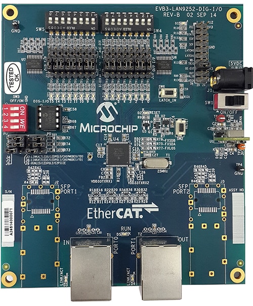
 Figure 2: This LAN9252 DIGIO board is a hardware-only EtherCAT secondary device that can operate without an attached MCU. The board allows for dual network connections to RJ45 sockets or fiber-optic interfaces for communications via an SFP module. This board is delivered preconfigured and on powerup will appear to a host as an EtherCAT secondary. (Image source: Microchip Technology)
Early origins and core elements of EtherCAT
One early improvement to Ethernet was ruggedizing the RJ45 plug-to-blue-cable connection. For use in industrial settings, this connector needed to be a tough and watertight connection capable of withstanding abrasions, impacts, and multiple flex cycles. Cable manufacturers that saw Ethernet as an enabling technology began introducing such connectors — at first for Industrial Ethernet (IE) control based on the standard TCP/IP protocol and the Open Systems Interconnection (OSI) seven-layer standard already in use.
 Figure 3: Industrial Ethernet cables ensure uncompromised data transmission and have a ruggedized abrasion-resistant construction to prevent costly downtime and maintain safe and secure machine operation. (Image source: Getty Images)
Such physical connections complemented new forms of industrial controls with data-collection cards on their motherboards — and capable of handling data and providing control signals for simple processes. It was a logical first step in the move towards more use of Ethernet in automation and for events that were not time critical (or process variables such as temperature, flow, and humidity that changed fairly slowly) such arrangements worked just fine.
However, automation control based on PCs was still out of reach: Packet collisions made timing inconsistent and tasks couldn’t be synchronized with the split-second timing needed for more advanced operations — as in high-speed production-line bottle inspection or flying-knife operations inside a packaging machine. Such automation demanded a new approach and several manufacturers came through with various solutions. The most widely adopted of these was EtherCAT.
First released in 2003, EtherCAT had (and still has) some of the fastest cycle times of Ethernet-based communication options, so it quickly became a preferred networking and control architecture for factory automation. One caveat: Getting the most out of EtherCAT (to satisfy industrial automation’s requirements for speed and determinism) necessitated that the bus be complemented by fast control hardware; which in many cases relies on application-specific integrated circuits or ASICs within the controls handling EtherCAT functionality.
Basic structure of EtherCAT for determinism
EtherCAT uses the telegram structure of Ethernet data to establish a primary (master control) and its relationship with secondary (node) sensors and actuators on the factory floor. Those small inexpensive ASICs reside in each node to boost the performance of this configuration.
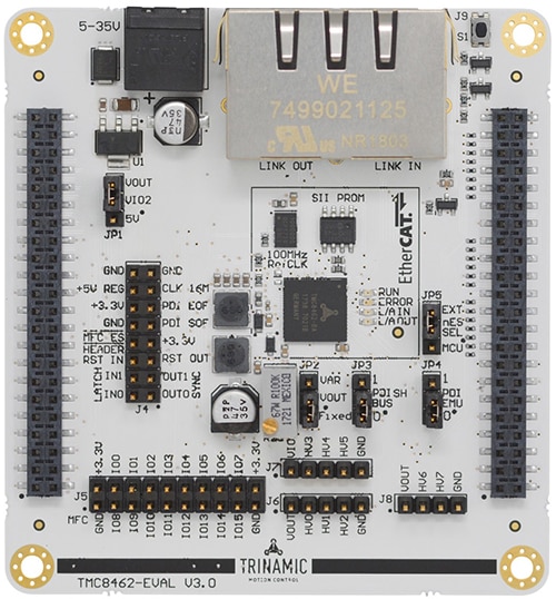
 Figure 4: TMC8462 EtherCAT secondary controllers with 100 Mb physical layers (PHYs) are capable of real-time communications. Their dual-switch-regulator power supply and 24 V I/Os complement the speeds in industrial environments. The secondary MC8462 controllers usually pair with watchdog, PWM, and SPI/I2C primary units for advanced capabilities in either device-emulation mode or with an external CPU. (Image source: TRINAMIC Motion Control)
Here’s how it works: A telegram traveling along EtherCAT’s ring topology starts at the primary controller and travels through all the nodes. At every node there are instructions ready to be offloaded as well as data packets ready to add their information to the telegram. Without slowing down as the telegram passes through the node, each node’s ASIC orchestrates a high-speed exchange of information and then the telegram speeds off to the next node. Once it’s made a complete round, everything is updated within the controller and another data packet is sent down the track. This scheme is inherent to the EtherCAT structure and prevents packet collisions while ensuring that data is instantly available to the controller at the end of every cycle. Only the primary (controller) is allowed to release a telegram.
This example uses a ring topology, but it is a full-duplex system, so if the last node in a segment is open, that node sends the packet back up the line to the primary.
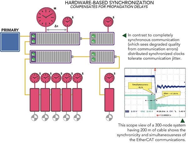
To ensure deterministic data, EtherCAT uses a distributed clock. Here, the primary controller sends a packet to all nodes which in response latch their internal clock twice — first when the packet is received and then again when it returns to the primary. Such a routine (which in fact can be repeated several times) provides a direct measurement of the propagation delay associated with each node. Then the resultant calculated delays are loaded into an offset clock. Finally, the primary sets the first node in the sequence as a reference clock for all the other nodes on the bus.
EtherCAT can be configured to update this delay periodically, or even with every cycle. The combination of rapid data cycle times and the distributed clock allows the whole system to operate with less than 0.1 msec of jitter at a data rate of 100 Mbit/sec, capable enough for most industrial tasks.
 Figure 5: Key to high-performance control of automated machines are minimum response time along with deterministic value acquisition and output. It makes no difference when exactly communications and calculations occur — as long as results are available in the output component before the next required output. EtherCAT delivers this functionality so that upon some input (value acquisition) into a discrete EtherCAT control loop, that value travels (communicates) to the controller which then calculates a response. (Image source: EtherCAT Technology Group)
EtherCAT has another built-in time management feature as well. Certain sensors, actuators, and systems are critically dependent on real-time control; servomotors, safety equipment, and elevators are just a few examples. EtherCAT systems can be setup to support these components and systems by allowing the programming of the system’s primary controller to give preference to critical data. Less critical components then get fewer data requests and updates, while critical components get more frequent data requests and updates.
Timeline of newest EtherCAT features
The core of EtherCAT traces its roots to Beckhoff Automation’s Lightbus (released in 1989) and Fast Lightbus (employing Ethernet cables) in 2003. In 2005, the EtherCAT specification was published and in 2007 was codified in IEC 61158 as a fieldbus standard. With a legitimized international standard, Beckhoff and other manufacturers were quick to develop physical hardware and software to leverage EtherCAT capabilities while maintaining backward compatibility.
Managing the EtherCAT standard is the EtherCAT Technology Group (ETG) — an industry group of OEMs and end users who share developments and ensure the interoperability of EtherCAT-compatible devices. Among many other things, this group has developed a compatibility tester called the Conformance Test Tool (CTT) for verifying that new devices meet the interoperability standards.
Strong acceptance of EtherCAT by an array of industries has supported its continuous innovation.
2008: Distributed clocks with XFC — The distributed timing characteristic so core to the operation of EtherCAT communications was covered in the previous section of this article. However, it’s worth adding that the distributed EtherCAT clock is part of Beckhoff’s eXtreme Fast Control (XFC) technology requiring that all EtherCAT devices have their own clocks that continuously synchronize with all other clocks on the EtherCAT system. EtherCAT compensates for various components’ differing communication runtimes for deviation between clocks held to below 100 nsec. Timestamped data is used to refine the timing of a specific control parameter within a single telegram. The distributed system clock ensures that all system clocks are synchronized to within less than 100 nsec, and the timing of a control event is normally limited by the cycle time. With XFC, timestamped data allows for activation (and events) between data cycles for quick and highly precise control — and at a 200 kHz data-sampling rate for minimal data noise.
 Figure 6: This gateway allows the connection of serial RS-232/422/485 components to EtherCAT control systems. Called the Anybus Communicator, it executes intelligent protocol conversion to send serial data to the primary PLC or controller as simple I/O data. (Image source: HMS Connecting Devices)
2010s: Various EtherCAT development-software environments — Initial introduction of EtherCAT spurred release of software to ease integration, with a widening array of software being offered with modules to simplify the integration of application-specific automation functions. The first of these modules were aimed at the machine-tool industry and the PLC, NC, CNC, and robotics controls it requires. Today, software to facilitate the use of EtherCAT is increasingly compatible with IEC 61131-3 code as well as programming from C/C++, Visual Studio, MATLAB, and Simulink environments. The latter development allows for building, simulating and optimizing control systems before implementation.
2011: EtherCAT cables to simplify power and data into servo axes — For years, integrators of motion systems (so ubiquitous in automation) complained about how servo axes necessitated multiple cables for electric-motor control, power, and feedback. Using a single cable for carrying power and mixed signal types at different voltage levels can create signal noise, level shifts, and crosstalk. But about 10 years ago, motion-component suppliers (with careful attention to cable jacketing, shielding, capacitance mitigation, and conductor sizes as well as arrangements) began bringing single-cable (power and data) EtherCAT cable solutions to market. Today these offerings (as EtherCAT P cable) serve servomotor axes as well as other compatible field devices.
2014 to 2017: More support of multi-axis and machine-vision systems — These years saw EtherCAT software allowing the stacking of hardware for expanding multi-axis installations with an array of built-in safety functions (such as STO, SOS, SS1, SS2), most useful in robotic and pick-and-place operation needing flexible and modular deployments. These years also saw more support of EtherCAT-based machine vision — a natural fit with EtherCAT’s inherently high-speed processing methodology easily supporting machine vision’s real-time data requirements. Some software even allows direct integration of machine-vision tasks into a machines’ programming for EtherCAT-based control for simplified inspection, robotics, and quality-control tasks.
2018: Faster versions of EtherCAT with backwards compatibility — EtherCAT G (with speeds of 1 Gb/sec) and EtherCAT G10 (with speeds to 10 Gb/sec) complement increasingly powerful automation controllers on the market while allowing use of original EtherCAT structures. With these networks, all processes are identical to original iterations of EtherCAT (including the distributed clock system), but the catch here is that some field devices struggle with the faster cycle times. The solution to this problem are EtherCAT branch controllers (connection nodes) to accommodate 1 Gb/sec loops as well as an array of 100 Mb/sec loops.
Since 2018: More EtherCAT hardware and software options and IoT support — Recent years have hastened the introduction of EtherCAT-networked industrial components and integrated systems. They’ve also seen software with machine-learning modules leveraging EtherCAT — along with cloud-based engineering and access via EtherCAT-compatible gateways. That means end users who own or use EtherCAT-networked machines can now swap source code, perform system simulations, and even leverage machine information for IoT analyses, which is particularly useful for end users operating machines in geographically separated manufacturing sites. As of mid-August 2020, more than 3,000 member company IDs had been issued to the ETG.
Conclusion
Almost 40 years ago, the industrial-automation industry began pursuing ways to leverage the ubiquity and power of Ethernet for industrial communications. Today Ethernet-based communications and control are anything but exotic — and in many settings serve as the gold standard. EtherCAT’s combination of features gives it one of the best performance-to-cost ratios of any of the Ethernet-enabled buses on the market today. With its support of Industry 4.0 and IIoT installation concepts, EtherCAT will remain indispensable for future transformations of automation.

Disclaimer: The opinions, beliefs, and viewpoints expressed by the various authors and/or forum participants on this website do not necessarily reflect the opinions, beliefs, and viewpoints of DigiKey or official policies of DigiKey.


