Understanding and Selecting Film Capacitors for Power Applications
Contributed By DigiKey's North American Editors
2025-05-08
Solar panel and electric vehicle (EV) use continues to increase. Their power systems rely on DC/DC converters and DC/AC inverters that require capacitors to reduce low-frequency ripple, filter high-frequency components that cause electromagnetic interference (EMI), and absorb transient load currents to prevent them from affecting the primary side of the power source. Capacitors for these power applications must be reliable, compact, lightweight, long-lived, and exhibit good high-frequency performance.
While film capacitors are a good option for these power applications, designers must understand their structure and characteristics to select the correct device.
This article provides a brief overview of film capacitors. It then discusses their selection and use in power applications using examples from Eaton-Electronics Division.
Film capacitors
Like all capacitors, film capacitors include two conducting plates separated by an insulating dielectric comprising a thin plastic film, typically made of polypropylene, a low-loss, high-strength dielectric (Figure 1). The conducting plates are thin metal foil or a thin layer of metal deposited on the dielectric. The foil and film are wound around a core, leads are attached, and the capacitor is enclosed in a plastic case and sealed with an epoxy resin, protecting the capacitor from the environment.
 Figure 1: A film capacitor consists of a wound core containing alternating metal and dielectric layers, sealed in a protective plastic case. (Image source: Eaton-Electronics Division, modified by Art Pini)
While film capacitors have a relatively low energy density, they offer high capacitance density and several other features. First, film capacitors are nonpolar; they can be used in AC and DC circuits. Their dry, solid dielectric offers higher reliability than capacitors with liquid or semi-liquid electrolytes, and they have a stable capacitance value with excellent temperature stability. Lower equivalent series inductance (ESL) and equivalent series resistance (ESR) support the effective handling of high ripple currents and make film capacitors well-suited for high-frequency applications. Perhaps the most significant characteristic of film capacitors is that they are self-healing. If a dielectric breakdown occurs, a local hot spot is created that vaporizes adjacent metal, forming a non-conducting hole and allowing the capacitor to function normally, thereby extending its life.
Film capacitor types
Film capacitors are tailored for specific applications, and the common types are safety, DC link, AC filter, and pulse. Safety film capacitors are designed to attenuate conducted emissions in AC-line filtering applications. Many international safety standards have requirements for conducted EMI. Consider a line-powered DC charger for an EV. In fast-charging DC stations, common and differential-mode EMI filtering via capacitors serve as a low impedance to shunt noise signals with minimal power dissipation.
EMI suppression uses line filters comprising film capacitors between the power line and the switching power supply (Figure 2).
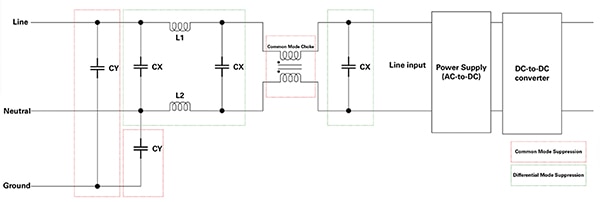 Figure 2: Safety film capacitors CX and CY are incorporated into line filters to prevent EMI from propagating to the power line. (Image source: Eaton-Electronics Division)
The capacitors marked CX are placed line to line and reduce differential-mode EMI. The CY capacitors are wired from each line to ground, reducing common-mode EMI.
DC link capacitors serve as smoothing filters in DC circuits found between AC stages. An example is an inductor-capacitor (L-C) filter on the DC bus between a motor drive circuit's rectifier and inverter stages (Figure 3).
 Figure 3: Shown is a DC link film capacitor used in an L-C filter between a motor drive circuit's rectifier and inverter stages. (Image source: Eaton-Electronics Division)
Along with motor drives, these capacitors are also often found in power inverters and other high-power charging circuits where the AC input and AC output have different voltage levels. For example, consider a distributed inverter in a solar power system, where a DC link film capacitor is used to reduce noise and transients between stages (Figure 4).
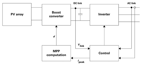 Figure 4: A DC link film capacitor suppresses noise and transients between a solar power system's boost converter and the inverter. (Image source: Eaton-Electronics Division)
The film capacitor reduces spurious signals at a point where the Vlink line feeds information back to the control circuit, improving performance.
AC filtering capacitors help eliminate unwanted harmonic frequency content in applications such as three-phase AC power sources (Figure 5).
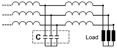 Figure 5: Shown are AC filter capacitors being used to filter a three-phase power source. (Image source: Eaton-Electronics Division)
Film pulse capacitors are designed to protect sensitive components from high dV/dt voltage changes. They are used in pulsed electronic and power inverter applications. Designed for high energy density, they provide fast bursts of power in circuits such as resonant tank power converters (Figure 6).
 Figure 6: The pulse film capacitor forms a resonant tank circuit tuned relative to the switching frequency of the power converter, eliminating harmonics in the transformer secondary. (Image source: Eaton-Electronics Division)
Resonant tank circuits significantly improve the efficiency of inductor-inductor-capacitor (LLC) power converters. The pulse capacitor is used to tune the tank circuit relative to the switching frequency of a power converter. The resonant tank eliminates harmonics from the secondary of the transformer. Additionally, the resonant tank enables soft switching in the power converter switches, reducing losses and increasing efficiency.
Film capacitor construction
The characteristics of each type of film capacitor are determined by the materials used and the geometry of the film layers. For example, Eaton-Electronics Division’s EFACA25J155D032LH AC filtering capacitor is a 1.5 microfarad (mF) ±5% capacitor with a maximum voltage rating of 250 V. It is AEC-Q200 qualified for automotive applications and has a THB type IIIB rating for humidity ingress.
Film capacitors are formed by alternating layers of the metalized dielectric. For the lowest voltage-rated capacitors (180 VAC to 300 VAC), the alternate layers are each connected to individual leads. Multiple layers in parallel increase the total capacitance, while placing two or more layers in series increases the voltage rating (Figure 7).
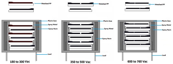 Figure 7: Adding multiple capacitors in series increases the voltage rating of a film capacitor. (Image source: Eaton-Electronics Division, modified by Art Pini)
The leads are connected to each side of a split metallization for a higher voltage rating (350 VAC to 500 VAC. The alternate layer has a single metalized film isolated from the leads and serves as a common capacitor plate, resulting in two capacitors in series. This structure increases the breakdown voltage of the pair while lowering the capacitance. By placing multiple pairs in parallel, designers can increase the capacitance.
Using the same principle of isolated split segments, the 600 VAC to 760 VAC-rated capacitors create three series capacitors for every set of overlaid pairs.
Pulse capacitor applications and construction
Pulse capacitors are designed for applications that experience high dV/dt and currents. They exhibit low ESR and ESL, which improves their ability to absorb energy from transient voltage spikes. Their self-healing properties ensure reliable long-term operation.
Pulse film capacitors are well-suited for snubber applications in switched-mode power supplies, where they protect active switching devices from voltage spikes and ringing that occur during switching. For example, in Figure 8, a pulse film capacitor (C1) combined with a resistor (R1) and a diode (D1) forms a snubber that absorbs voltage spikes generated by the parasitic inductance of the transformer during the turn-off of the MOSFET switch.
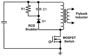 Figure 8: Pulse film capacitors such as C1 are well-suited to snubber applications in switched-mode power supplies, where they absorb voltage spikes generated by the parasitic inductance of the transformer during the turn-off of the MOSFET switch. (Image source: Art Pini)
When the MOSFET opens in a flyback switched-mode power converter, the drain current is at its maximum. The inductance of the transformer operates to maintain that current and rapidly raises the voltage. Initially discharged, the capacitor in the snubber circuit absorbs the inductive spike energy, protecting the MOSFET switch. The response time of the capacitive action is reduced by keeping the ESL low, allowing the snubber to handle the high dV/dt of the transient. The low ESR permits the high currents needed to absorb the transient energy during the switch turn-off.
The construction of the pulse film capacitor is optimized to handle high dV/dt and resulting currents (Figure 9).
 Figure 9: The internal structure of a pulse film capacitor employs a double-sided metalized dielectric film to reduce ESR. (Image source: Eaton-Electronics Division)
Eaton-Electronics Division film pulse capacitors use a double-sided metalized dielectric film, effectively doubling the contact area between the capacitor plate and lead connection, thereby lowering the capacitor’s ESR and increasing its current capability. For example, the EFPLS1GJ223B072LH is a 0.022 mF ±5% pulse film capacitor rated for a maximum voltage of 1600 V. It has an ESR of 30 milliohms (mΩ) and an ESL of 12 nanohenries (nH). It has a maximum dV/dt specification of 6,000 V per microsecond (V/µs) and an RMS current rating of 3.2 A, with a peak current rating of 132 A.
The related EFPLA series includes pulse film capacitors for severe environments, such as automotive, and conforms to THB Grade IIIB and AEC-Q200 specifications. The Eaton EFPLA2AJ153B092LH, for example, is a 0.015 mF ±5% pulse film capacitor rated for 2,000 V. It has an ESR of 45 mΩ and an ESL of 12 nH. It has a maximum dV/dt specification of 4,500 V/µs and an RMS current rating of 3 A, with a peak current rating of 142.5 A.
Conclusion
Film capacitors utilize dry, non-polarized technology and feature high capacitance density. They offer stable capacitance over temperature, handle high ripple currents and pulse and surge voltages, and are suitable for high-frequency and power applications. Their metalized construction also provides a self-healing capability, enhancing reliability and operational life and facilitating a more graceful failure mechanism. Eaton-Electronics Division offers a broad and growing range of metalized polypropylene film capacitors functionally optimized for multiple distinct applications and operating environments.

Disclaimer: The opinions, beliefs, and viewpoints expressed by the various authors and/or forum participants on this website do not necessarily reflect the opinions, beliefs, and viewpoints of DigiKey or official policies of DigiKey.


