The Basics of Motor Contactors and Their Application
Contributed By DigiKey's North American Editors
2023-04-05
Applications such as heating, ventilation, and air conditioning (HVAC), compressors, pumps, material handling, and packaging, require the safe deployment and control of large motors operating off high voltages and currents. Controlling these large electric motors poses a problem for designers in that they must provide adequate isolation between the motor and the control circuit. In addition, the high voltages and currents can generate significant electromagnetic transients that can damage electronic controls.
Electromagnetic relays offer remote control with isolation but have their own limitations. Opening and closing the power connections to a high-power motor generates electric arcs which wear the relay contact surfaces, reducing the contact lifetime.
The solution to this problem is an electromagnetic contactor, a special class of relay intended for motor control. In addition to more rugged construction and larger, more robust contacts than relays, they employ arc suppression techniques that include special materials and faster contact closing and opening.
This article examines the basics of electromagnetic motor contactors and their advantages over other approaches to motor control. It then discusses how they are selected and applied using real-world configuration examples from the Schneider Electric Easy TeSys family.
How contactors work
Electromagnetic contactors consist of an electromagnet built on an ‘E’ core. Specifically, an electrically isolated coil is wrapped concentrically about the center leg of the core. The coil is excited by the controlling voltage source, which may be AC or DC. When the coil is energized, the electromagnetic force pulls in an armature located at the core’s open end (Figure 1).
 Figure 1: A simplified functional diagram of a contactor showing it in both the de-energized and energized states. (Image source: Art Pini)
Electrical contacts are mechanically coupled to the armature. The contact arrangement varies by contactor model: they may be normally open (NO) or a combination of normally open and normally closed (NC). There may be multiple isolated contacts. For instance, a 3-phase contactor will have three sets of power contacts, one for each phase. When the armature pulls in, the NC contacts open, and the NO contacts close. Additionally, many contactors include an auxiliary set of lower power contacts that are used to monitor the state of the contactor, energized or de-energized.
Contact materials are chosen for high strength, excellent electrical conductivity, and resistance to the effects of arcing and oxidation. The contact geometry is designed to handle the intended power levels and to suppress arcing.
All the elements of the contactor are contained in an enclosure, which electrically insulates the contacts while providing a simple method for connecting power, load, and coil wiring. The enclosure also provides mounting support, which may be in the form of panel or DIN rail mounting (Figure 2).
 Figure 2: Examples of typical contactor enclosures; panel mount (left) and DIN rail mount (right). (Image source: Schneider Electric)
The Schneider Electric Easy TeSys (DPE series) contactors are housed in a compact enclosure that is only 45 millimeters (mm) wide and can be mounted to a panel or a DIN rail. The enclosure has an ingress protection rating of IP20, indicating protection for fingers. All contactors in the series include a normally open auxiliary contact. This series of 3-phase contactors is UL/CSA approved with ratings up to 32 amperes, 20 horsepower at 480 volts AC (HP/480 VAC) and 25 HP/600 VAC, with a variety of control coil excitation voltages (Table 1).
|
Table 1: Selected examples from the Schneider Electric Easy TeSys DPE contactor series show the range of operational current and control coil voltage selections the line provides. (Table source: Art Pini)
These devices offer an operational life of approximately 1 million electrical operations. Easy TeSys contactors are suitable for applications described in the utilization categories specified in standard IEC 60947. The current ratings of the individual contactors depend on the utilization category. For example, The AC-1 category describes applications where the load is non-inductive or only slightly inductive, such as a resistance-based furnace. These applications have primarily resistive loads, which have less of an issue with transient voltages and currents.
Category AC-3 covers applications for squirrel cage induction motors where the motor is started, and power may be removed to stop the motor at times. Motors are inductive devices and starting and stopping operations result in inductive transients that place a greater strain on the contactor.
Applications in the AC-4 category place greater stress on the contactor. This category covers squirrel cage induction motors and slip ring type motors subject to reverse current braking and jogging or inching. Jogging or inching is "the quick repeated application of power to start a motor from rest for the purpose of accomplishing small movements of the motor.” Jogging generally refers to starting a motor with short pulses of power at full voltage. Similarly, inching means starting a motor with short pulses of reduced voltage. The multiple applications of power generate the highest level of stress on the contactor.
Matching a specific Easy TeSys DPE contactor to a motor or similar high-power application is based primarily on the current being handled. The Schneider Electric Easy TeSys catalog contains selection aids based on the motor power, utilization category, and the operational lifetime required (Figure 3).
") Figure 3: The Easy TeSys DPE selection guide for AC-3 utilization category motors based on motor power and desired contactor operational life. (Image source: Schneider Electric)
Figure 3: The Easy TeSys DPE selection guide for AC-3 utilization category motors based on motor power and desired contactor operational life. (Image source: Schneider Electric)
Figure 3 is one of three selection guides related to the utilization category of the device being controlled. It is for utilization category AC-3, basically a motor that may be stopped infrequently. When the motor is stopped, the current is equal to the operational current. As an example, consider finding an Easy TeSys DPE contactor for a 5.5 kilowatt (kW), 3-phase motor operating at 400 volts with an operational current of 11 A where the desired operational life is two million cycles. Starting on the 400-volt voltage line, the designer needs to locate 5.5 kW, and from there, project a line upward until it intersects the two million operations line. The nearest DPE model locus (in blue) is the DPE 18.
An example of an AC-4 utilization category, where the motor is stopped and restarted frequently, deals with larger worst-case currents. Consider a 3-phase, 5.5 kW motor running at 400 volts with an operational current of 11 A in an AC-4 application in which it is de-energized while the motor is stalled. The desired operational life is 300,000 operations.
The stalled current for this motor is six times the operational current, requiring a contactor rated for a higher current level (Figure 4).
") Figure 4: The Easy TeSys DPE selection guide for the AC-4 Utilization category. Note that the worst-case currents can be much larger due to the possibility of power being removed from the motor while it is stalled. (Image source: Schneider Electric)
Figure 4: The Easy TeSys DPE selection guide for the AC-4 Utilization category. Note that the worst-case currents can be much larger due to the possibility of power being removed from the motor while it is stalled. (Image source: Schneider Electric)
To find the recommended contactor, start with the stalled current of 66 A, which is six times the operational current of 11 A. Projecting upward from the current axis until it intersects the line representing 0.3 million operations. The nearest product locus is the DPE32.
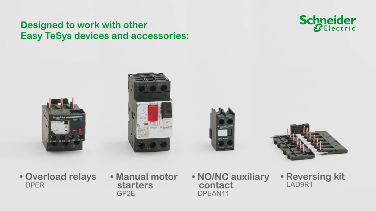
The Easy TeSys DPE series contactors cover the most common motor configurations and applications, such as conveyors, packaging machines, pumps, compressors, heating and ventilation, air conditioning, refrigeration, and more.
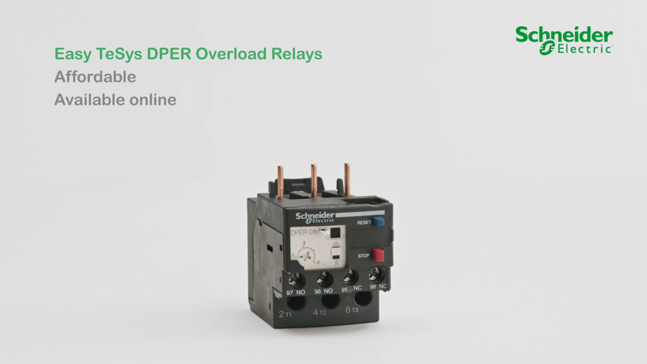
The Easy TeSys family also includes a series of complementary thermal overload relays designed to protect AC circuits and motors against overload, phase failures, extended starting times, and stalled rotor conditions. These relays monitor the motor current, and when the current exceeds the current limit setting, the contacts open and stop the motor. There are fifteen different models, and each has a range of settable current trip levels. The overload protection models are compatible with selected Easy TeSys contactors DPE09 through DPE38. They connect directly to the bottom terminals of the 3-phase contactors using the contactor’s screw clamp terminals. The combination has a common 45 mm width and can be mounted on DIN rail or screwed to a panel using the DPE contactor mount (Figure 5).
 Figure 5: The overload protection relay mounts directly under the DPE contactor and is fastened using the contactor’s screw clamp connections. (Image source: Schneider Electric)
The Easy TeSys DPER32 thermal overload relay, rated at 32 A/690 volts has an adjustable thermal setting trip range of 23-32 A, tripping class 10 (with an overload of six times the preset level, the overload protector will trip within 10 seconds), for protection of 3-phase motors rated at 15 kW@400 volts. It is a differential device with phase failure and load unbalance detection. It has a thermal adjustment dial, a manual/automatic reset selector, a test selector for the simulation of a trip, reset and stop buttons, a flag indicator, and two auxiliary contacts (1 NO + 1 NC) for fault signaling. The user settings are protected by a lockable transparent cover. The entire thermal overload protector family is certified under multiple standards, including IEC, UL, and CUL.
Conclusion
Designers of motor applications with high operating voltages and currents need a reliable way to isolate associated control circuits and protect them from electromagnetic radiation. The Easy TeSys three-pole DPE contactors, together with the DPER Easy TeSys thermal overload relays, are designed to switch and protect the most common motor use cases. The wide range of models covering multiple current and voltage levels makes it easy to configure them to a specific application’s requirements.
Disclaimer: The opinions, beliefs, and viewpoints expressed by the various authors and/or forum participants on this website do not necessarily reflect the opinions, beliefs, and viewpoints of DigiKey or official policies of DigiKey.