Terminal Blocks – What You Need to Know
2020-12-01
As a well-recognized component in any engineer’s connector toolbox, terminal blocks have been used for many years to provide semi-permanent, secure wire connections in a range of applications. Terminal blocks, also referred to as connection terminals, terminal connectors, or screw terminals, consist of a modular housing and insulated body that connects two or more wires together. Thanks to the semi-permanent nature of their connections, terminal blocks help to simplify the inspection and repair process in the field. Although a relatively simple component, it is still beneficial to have a baseline knowledge of terminal blocks and their specifications prior to selection. This article will discuss topics including common terminal block types, key electrical and mechanical considerations, and more in further detail to assist engineers in this process.
Common configurations
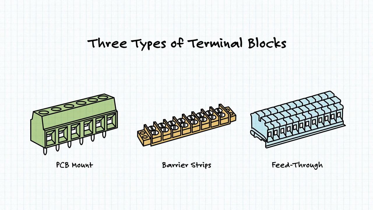
PCB mount, barrier strips, and feed-through are three of the most common terminal block types used in designs. The following table outlines the three different types, including their basic principles, mounting styles, and configurations.
|
Important electrical specifications
With the common types of terminal blocks now covered, there are a number of key electrical specifications that must be considered during the design phase. These include:
Current Rating: In general, the most important specification to note in terminal block designs is the current rating. This is built upon three areas: the conductivity of the terminals, cross-sectional area, and the corresponding temperature rise. When making a terminal block selection, it is recommended that the module carries a current rating of at least 150% of the system’s anticipated maximum current. If a terminal block is not properly rated and operated at too high of a current, overheating and damage to the terminal block can lead to critical safety concerns.
Voltage Rating: A terminal block’s voltage rating is partially influenced by the pitch and dielectric strength of its housing. Along the same lines as the current rating, a terminal block’s voltage rating must be greater than the maximum system voltage, while also considering any voltage surges that could damage the connections.
Pole Count: The pole count is the common way to express the number of individual circuits housed by a terminal block. This specification will generally range from a single pole up to as many as 24 poles.
Pitch: Defined as the center distance from adjacent poles, pitch is determined by the terminal block’s overall rating where factors like creepage, voltage/current, and clearance are concerned. Some examples of common pitches include values such as 2.54 mm, 3.81 mm, 5.0 mm, and more.
Wire Size/Type: Specified in units of American wire gauge (AWG) in North America, terminal blocks list the size or gauge of wire the module can accept to ensure wires will physically fit into the housing. Thankfully, most terminal blocks do afford some tolerance with the ability to house a range of wire sizes such as 18~4 or 24~12 AWG. In addition to wire gauge, wire type should be considered depending on the module type selected. Stranded or multi-core is ideal for screw terminals, while single-core wire is often paired with push-in style terminal blocks.
Important mechanical specifications
Next on the list are mechanical specifications, which relate to a terminal block’s footprint, orientation, and accessibility of its connections within a design. Important mechanical factors include:
Wire-Entry Orientation: Horizontal (90°), vertical (180°), and 45° are the three most common terminal block orientations. This decision will be reliant upon a design’s layout and which orientation creates the greatest fit and accessibility to the connections.
 Figure 1: Typical terminal block orientations (Image source: Same Sky)
Wire-Securing Method: Similar to orientations, there are three common wire-securing methods for terminal blocks: screw terminal, push button, or push-in. All three types are relatively true to their name. Screw terminal or screw type terminal blocks contain a screw that when tightened closes a clamp to secure the wire against the conductor. Push buttons function simply by pushing a button that opens a clamp to allow insertion of the wire and then closes the clamp on the wire once the button is released. With push-in terminal blocks, wires can be inserted directly into the housing, creating a connection without screws or buttons to open a clamp.
 Figure 2: Typical wire-securing methods (Image source: Same Sky)
Interlocking vs. Single-Piece: Terminal blocks can be constructed in interlocking or single housings. Typically available in 2 or 3 pole versions, interlocking terminal blocks give engineers the ability to quickly achieve varied pole counts or connect different colors of the same module type together. DIN rail terminal blocks operate in a similar manner by sliding individual units together on a metal rail. These are then finished with a compatible end cap to protect the housing on the outer most units once the desired configuration and number of poles is achieved. Single-piece terminal blocks unsurprisingly contain all poles in a single module, giving them more rigidity and ruggedness depending on the design requirements.
 Figure 3: Interlocking vs. single-piece terminal blocks (Image source: Same Sky)
Wire-to-Housing Method: When frequent connecting and disconnecting of the main connection is needed, pluggable terminal blocks are a good option. These work by inserting wires into a modular plug, which connects to a fixed receptacle on the PCB, making it easy to disconnect without having to handle individual wires.
 Figure 4: Plug and receptacle connections of a pluggable terminal block (Image source: Same Sky)
Safety ratings and additional considerations
UL and IEC are the main safety agencies used to certify terminal blocks. When looking at a terminal block datasheet, UL and/or IEC safety standards will be listed, most often with differing values. This is because each agency uses a different standard for testing, so it is important for engineers to know their overall system safety requirements in order to select a terminal block that will be in compliance.
While perhaps an afterthought in many designs, color customization of a terminal block’s housing or buttons can be beneficial. In choosing unique colors for terminal blocks, engineers can make it easier to link up connection points in complex systems and avoid improper connections.
Lastly, terminal blocks with higher temperature ratings are also an option in environments or applications dealing with extreme temperatures.
Conclusion
With an understanding of key electrical and mechanical specifications as well as different module types, engineers can be better equipped to meet the needs of a variety of electrical system connections. Same Sky terminal blocks product line offers engineers an array of color options and configurations to simplify this selection process.
Disclaimer: The opinions, beliefs, and viewpoints expressed by the various authors and/or forum participants on this website do not necessarily reflect the opinions, beliefs, and viewpoints of DigiKey or official policies of DigiKey.