Specifying and Using VFD Cables to Improve Reliability and Safety and Reduce Carbon Emissions
Contributed By DigiKey's North American Editors
2023-10-25
Variable frequency drives (VFDs) and motors can reduce carbon emissions and increase efficiency, reliability, and safety across various systems, including conveyors, pumps, mixers, elevators, heating ventilation/air conditioning (HVAC) systems, and similar applications. The cabling that connects the VFD to the motor is a critical link in the system. Without correct cabling, operator safety can be marginalized, and motor reliability and operating life can be reduced.
Typical VFD systems operate in harsh conditions that include high voltage spikes reaching two to three times the supply voltage and high levels of radiated and conducted electromagnetic noise. In addition, the cables can be exposed to high temperatures. They must resist oil, water, and ultraviolet (UV) radiation while maintaining a high degree of flexibility and meeting numerous technical requirements from UL, CSA, NFPA, and NEC.
Challenging operating environments and technical demands for VFD installations complicate cable specification. This article briefly reviews the operation of VFDs and motors, the demands on cable insulation, and the need for electromagnetic compatibility (EMC). The article compares specifications like UL 1277 TC ER, WTTC, and TC cables and examines NEC and NFPA requirements. It also presents cable structure considerations before closing with an overview of exemplary cables from Belden, Helukabel, Igus, LAPP, and SAB North America.
Environmental challenges
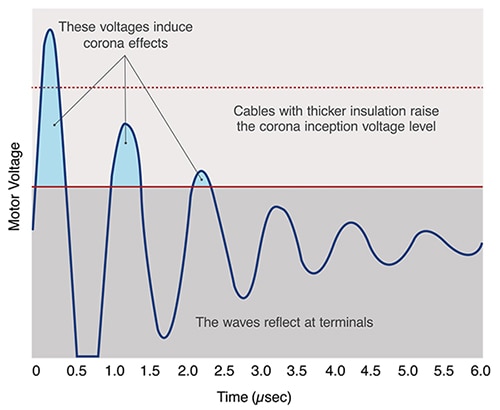
VFD motors, drives, and the cables that connect them operate in harsh electrical environments. VFD cables need to efficiently deliver high drive power at high voltages and handle high voltage spikes and high noise levels. The insulation in VFD cables is subjected to challenging conditions such as reflected waves and corona inception voltages (Figure 1):
- Reflected waves: Reflected waves can be caused by mismatched impedances between a VFD's motor and its cable. That can cause voltage waves to bounce back to the drive. Without high-performance insulation, reflected waves can break down the insulation and overheat the cable.
- Corona inception voltage/corona discharge: The pulse width modulation (PWM) voltages in VFD systems rapidly oscillate from zero to peak voltage. Without proper insulation, a high voltage spike occurring above the cable's corona inception voltage causes the air around the conductor to become ionized, resulting in corona discharge that can melt the insulation and damage the motor, the motor bearings, and the drive.
 Figure 1: VFD cable insulation must handle reflected waves and corona inception voltages. (Image source: SAB North America)
Shielding and grounding
In addition to withstanding voltage spikes, VFD cables must support high levels of EMC. Important EMC considerations include the following:
- Common mode currents result from the three-phase voltages in VFDs that don't sum to zero, creating a voltage imbalance. When the non-zero voltage level changes, a proportional cable charging current returns through the grounding conductor. Excessive common mode current creates a ground loop that interferes with proper system performance.
- Transmitted electrical noise results from the variable drive frequencies that can induce electromagnetic (EMI) and radio frequency interference (RFI) and affect nearby components and systems.
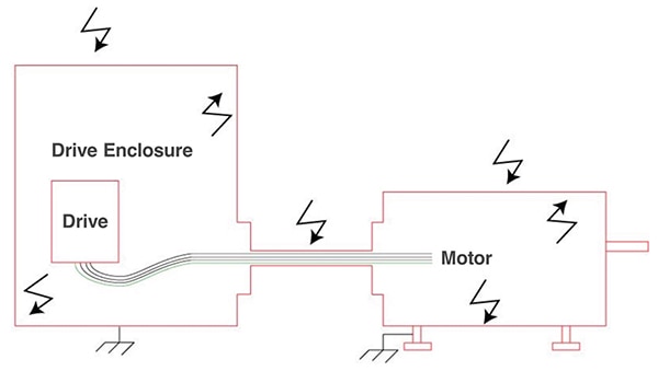
An effectively grounded drive, cable, and motor system creates a Faraday cage that ensures robust EMC performance (Figure 2).
 Figure 2: VFD cables can mitigate common mode currents and electrical noise with proper grounding connections. (Image source: SAB North America)
Glands vs. conduit
VFD cables are available with small diameters for running in conduit and as continuously welded armored cable structures. These solutions require complex, costly installation and suffer from potential reliability problems. Tray cables (TCs) are available that don't require conduit. When a conduit is available, it can be used to create the Faraday cage between the drive and the motor. When various classes of TCs are used, EMC cable glands can be added to complete the Faraday cage. EMC cable glands provide ingress protection (IP) ratings of 68 that are water resistant in fresh water to a maximum depth of 1.5 meters for up to 30 minutes and are protected from dust, making them suitable for use in challenging industrial and outdoor environments (Figure 3).
 Figure 3: Cable glands can be used on the connections to the drive electronics and the motor to create a Faraday cage and control EMI. (Image: SAB North America)
Cable classes
TCs can simplify installation and reduce costs. Various application criteria, like voltage rating, flexibility, and crush/impact tests, classify them. There are two main UL standards. Both standards apply to cables that are 18 AWG and larger. The two standards are:
UL 1277, Electrical Power & Control Tray Cables, covers several types of TCs rated for 600 V.
- Basic TC cables are the most common type and are used as VFD cables where flame retardant properties are required.
- TC-ER (exposed run) tray cables must pass more rigorous crash and impact requirements than the standard TC cable. They can run free between cable trays for an average distance of 6 feet (1.8 m).
- THHN/PVC is a low-cost form of TC construction with a thermoplastic jacket. It is suitable for direct burial and for running in conduit.
UL 2277, Flexible Motor Supply Cable & Wind Turbine Tray Cable, covers two TC types rated for 1,000 V.
- Flexible Motor Supply Cable (FMSC) is primarily designed as a VFD motor power cable.
- Wind Turbine Tray Cable (WTTC) can withstand extreme, harsh conditions in wind applications like oil, abrasion, extreme temperatures, water, constant movement, and so on.
NEC and NFPA
NEC 79/NFPA 79 2018 Edition compliance is often, but not always, required in the U.S. depending on the local building codes. The standard requires that VFD cables must be marked RHH, RHW, RHW-2, XHH, XHHW, or XHHW-W defined as follows:
- RHW, RHH, and RHW-2 use a high-heat rubber insulation.
- RHW indicates a water-resistant cable with a temperature rating of +75°C
- RHH indicates a cable with a temperature rating of +75°C that is not water-resistant
- RHW-2 indicates a water-resistant cable with a temperature rating of +90°C
- XHH, XHHW, and XHHW-W use XLPE (cross-linked polyethylene) insulation.
- XHH is for use in damp locations and rated for +75°C
- XHHW is for use in wet locations and rated for +75°C
- XHHW2 is for use in wet locations and rated at +90°C
XLPE insulation is lighter and more flexible than rubber insulation, making XLPE cables easier to install, especially in low temperatures. Additionally, XLPE offers lower leakage compared to rubber insulation.
Cable construction
There are numerous ways to implement VFD TCs. Part number CF31-25-04 from Igus is a good example of many of the common elements; the numbers in the list correspond with Figure 4:
- Outer jacket made using pressure extruded, oil-resistant PVC mixture Outer jacket Low-adhesion, oil-resistant PVC
- Outer shield made using highly bend-resistant braiding consisting of tinned copper wires
- Inner jacket of pressure extruded gusset-filling PVC
- CFRIP is an Igus-specific tear strip molded into the inner jacket for faster cable stripping
- Core insulation of cross-linked polyethylene plastic (XLPE) has a three-dimensional bond within the plastic; XLPE has high mechanical strength and low capacitance
- Conductor that varies for cores < 10 mm² and cores ≥ 10 mm² based on DIN EN 60228 requirements
- Central strain relief, a tensile stress-resistance material
 Figure 4: Example of a VFD cable illustrating the shielding and strain relief elements in addition to the current carrying conductors. (Image source: Igus)
More choices
LAPP's ÖLFLEX VFD 1XL is a family of robust oil-resistant and UV-resistant shielded VFD drive cables for designs that need a smaller cable diameter. The unusually small diameter of the XLPE insulation makes these cables suitable for use in crowded installations where standard cables can be too large. In addition, the thinner diameter supports increased flexibility to speed installation. These TC-ER-rated cables can be installed without a conduit, but their smaller diameter and flexibility simplify using conduits when needed. They meet XHHW2 performance requirements. For example, LAPP offers several models with four conductors (including the ground) plus drain, like model 701703 with 10 AWG (5.3 mm²) conductors and model 701717 with 2 AWG (33.7 mm²) conductors.
Helukabel offers several cables with TC-ER and WTTC ratings, and they offer conductors from 2 to 18 AWG such as the four-conductor 12 AWG TC model 63141. They feature double shielding that combines aluminum foil (100% coverage) and tinned copper braid (about 85% coverage). They use XLPE insulation and have PVC jackets that are resistant to oil, coolants, solvents, and cleaning/disinfecting agents. These cables are rated for open, unprotected installation in cable trays and from the cable tray to the machine. Furthermore, they are suitable for installation in conduit or direct burial.
High flex cables
Belden offers multiple families of TCs with various conductor and ground configurations using several insulation and shielding materials (Figure 5). For installations that demand highly flexible TCs, the company offers its HighFlex VFD cables with several ranges of flexibility and up to 10 million flex cycles. These TCs feature finely stranded tinned copper conductors, with some models having over 2,000 individual strands and a flexible TPE jacket that makes them pliable for ease of handling during installation. For example, part number 29501F 0101000, with TC-ER and WTTC ratings, is designed for continuous movement and on-machine applications and meets the requirements of XHHW2 for use in wet locations at up to +90°C. Target applications for HighFlex VFD cables include:
- Running process equipment
- Powering pumps
- Driving fans
- Running material conveyors
- Moving robotic arms
 Figure 5: A few of the many conductor and ground configurations and insulation and shielding materials used in VFD cables. (Image source: Belden)
SAB's VFD cables are designed to provide optimized EMC performance. A design suited to continuous flexing is also available. These cables meet TC-ER and WTTC requirements, and they use XLPE insulation for improved capacitance with two options: one with a reduced diameter and one that supports longer runs. Different VFD motor makers have different pair size requirements for combo VFD TCs and may require a cable with or without a drain wire. SAB's VFD cables include cables that address most application requirements like power with a combo pair for brake or temperature sensing, multiple pair size options including 18, 16, 14, and 12 AWG, and some designs with two pairs. They have double shielding that combines foil with tinned copper braiding, and ground symmetrical designs are an option. These cables feature a bend radius 12 times the cable diameter and are XHHW2-rated for use in wet locations at up to 90 °C. A good example of these cables is the model 35661204, a four-conductor 12 AWG cable.
Conclusion
VFD cables are used in harsh electrical environments and must withstand high temperatures, exposure to water, oil, and/or various chemicals. Specifying those cables is a complex process, necessitating the consideration of various insulation properties, including the ability to withstand reflected waves and corona inception voltages, shielding, cable glands for EMC protection, and UL, NEC, and NFPA requirements. Correctly specified and installed VFD cables contribute to simplified and lower-cost installations, improved motor operation, fewer carbon emissions, and better operator safety.

Disclaimer: The opinions, beliefs, and viewpoints expressed by the various authors and/or forum participants on this website do not necessarily reflect the opinions, beliefs, and viewpoints of DigiKey or official policies of DigiKey.


