Select and Implement the Right Motor Control Design to Meet Industry 4.0 Requirements
Contributed By DigiKey's North American Editors
2022-09-13
The era of Industry 4.0, or the Industrial Internet of Things (IIoT), is making systems smarter by providing localized intelligence and connectivity between machines and computers, and to the Internet. One of the reasons for this connectivity is that production systems and subsystems can be monitored and controlled with a view toward greater efficiency, reliability, and stability. This era has implications for industrial motors, which comprise much of an automated facility’s energy resources, and where their failure can shut down an entire production line.
It follows then that it is critical to control motors effectively, particularly with respect to speed and torque, which together greatly impact a motor's dynamic range. Controlling these two parameters effectively requires a high degree of feedback accuracy. For this accuracy, designers need to choose carefully between low-side, high-side, or in-line current sensing, and then optimally implement the appropriate circuitry.
This article briefly discusses these three current-sensing options before showing how the ideal amplifier in an in-line motor current sensor provides true current-phase information. It then shows how to use a Maxim Integrated bidirectional current sense amplifier (CSA) with pulse width modulation (PWM) rejection to configure a three-phase motor system to enable more efficient operation.
Low-side, high-side, or in-line current sensing?
The three sensing options—low-side, high-side, and in-line—vary widely in implementation (Figure 1). The low-side motor current sensor design uses a sense resistor and amplifier close to ground (bottom left).
 Figure 1: The low-side, high-side, and in-line circuit options for motor speed and torque sensing. (Image source: Analog Devices)
Of the three options, a low-side current sensing circuit is the most intuitive and straightforward. It is suited to consumer applications where cost-effectiveness is frequently one of the primary design requirements.
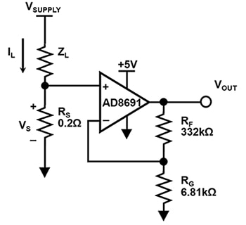
The low-side sensing circuitry has the amplifier near ground, capturing each leg’s current in succession. The circuitry has general-purpose, low-cost operational amplifiers (op-amps) at the bottom of the gate-driving FET stacks and a sense resistor (RS) with the common-mode voltage close to ground (Figure 2). For a load current as high as 100 amperes (A), the small sense resistor (RS) is usually a pc board trace resistance.
 Figure 2: This AC motor low-side current sensing circuit uses a CMOS amplifier where the common-mode voltage reaches the amplifier negative supply. (Image source: Bonnie Baker)
In Figure 2, the load current indicates the conduction through one AC motor’s FET stack. This circuit needs the amplifier’s common-mode input range to span to ground. The amplifier circuit gains the voltage across RS, which provides a voltage reading of the magnitude of the load current (IL). This voltage is fed to the non-inverting input of an amplifier with a gain equaling (1 + RF / RG), or ~50 volts/volt.
The Analog Devices AD8691 can be used as the amplifier. This is a low-cost, generic op amp with a bandwidth of 10 megahertz (MHz). Its CMOS input transistors render a typical input bias current of 0.2 picoamperes (pA) and a common-mode range that is -0.3 volts below the negative supply voltage.
The amplifier’s output is fed to an analog-to-digital converter (ADC). A microcontroller or other processor can use the digitized signal to determine the motor’s status.
PC board requirements
The low-side current sensing circuit’s design simplicity can be misleading. Using the pc board to create RS, it is easy to generate measurement errors by unintentionally adding to the sense resistor value. To ensure that the RS value is accurate, there must be a direct connection from the RS’ top or positive terminal to the non-inverting op-amp terminal. In addition, RS’ bottom (negative) terminal must have a direct ground connection. This second pc board design requirement ensures a direct connection to the sense resistor's negative terminal and the bottom of the amplifier's gain resistor (RG).
Take note that current flows through the ground plane of the pc board, creating a voltage difference across it. Under normal circumstances, this is not an issue. With the low-side sensor circuit, the use of the low RS resistance makes the circuit extremely sensitive to ground voltage drops across the pc board.
The copper resistance temperature coefficient is about 0.4%/°C, allowing the value of Rs to vary widely with temperature. The pc board resistance creates a temperature-dependent error in systems that have wide temperature variations, introducing a degree of instability. It is prudent to avoid long traces to minimize RS errors. In addition, the low-side sensor design’s use of a sense resistor adds undesirable dynamic voltage drops, causing electromagnetic interference (EMI) noise problems.
High-side current sensing
The high-side motor current sensor minimizes the resistor’s dynamic AC voltage impact with minimal EMI. However, this design necessitates a robust amplifier to handle high voltages.
The low-side current sensor circuit uses three single op amps to sense the currents of each AC motor leg. The approach is susceptible to errors due to parasitic pc board resistances, as well as near-ground measurement error, also called RS voltage ground error.
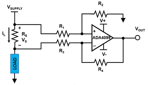
High-side current sensor circuits use a differential amplifier with the common-mode voltage close to the supply. To contrast some of the limitations of the low-side current sensor circuit, this configuration is not susceptible to ground disturbances and is capable of detecting a load short (Figure 3).
 Figure 3: An AC motor, high-side, current-sensing circuit uses an amplifier with two PNP input stages where the common-mode voltage reaches beyond the amplifier’s positive and negative supply. (Image source: Bonnie Baker)
The op amp must have rail-to-rail input and a large common-mode voltage at the RS terminals that equals or surpasses VSUPPLY. This is challenging because the sense amplifier will need extended voltage sources at least equal to VSUPPLY. Hence, in a high-side sensing configuration, the input common-mode of the amplifier needs to be as high as the supply voltage, VSUPPLY.
For this application, designers can turn to Analog Devices’ ADA4099-1. It is a single, robust, precision, rail-to-rail input/output op amp with inputs that operate from V- to V+ and beyond. The latter feature is referred to in the datasheet as Over-The-Top.
The device features an offset voltage of <40 microvolts (μV), an input bias current (IB) of <10 nanoamperes (nA), and operation on single or split supplies that range from 3.15 to 50 volts. The ADA4099-1 draws 1.5 milliamperes (mA) of quiescent current per channel.
Resistor matching
With the high-side current sensing circuit in Figure 3, the accuracy of the external resistors (R1, R2, R3, and R4) directly determine the measurement accuracy. Equation 1 is used to calculate Figure 3’s differential gain:
![Gd = 1/2 [R2/R1 [1+R4/R3]/[1+R2/R1] + R4/R3] Equation 1](http://sc-b.digikeyassets.com/-/media/Images/Article%20Library/TechZone%20Articles/2022/September/Select%20and%20Implement%20the%20Right%20Motor%20Control%20Design%20to%20Meet%20Industry%204.0%20Requirements/article-2022september-select-and-implement-the-right-equation1.jpg?la=en&ts=f4cd6363-f375-4324-8d66-dab633d4789a) Equation 1
Equation 1
Equation 2 is used to calculate Figure 3’s common-mode gain error:
![GCM = [R1/R2 [1+R4/R3]/[1+R2/R1] - R4-R3] Equation 2](http://sc-b.digikeyassets.com/-/media/Images/Article%20Library/TechZone%20Articles/2022/September/Select%20and%20Implement%20the%20Right%20Motor%20Control%20Design%20to%20Meet%20Industry%204.0%20Requirements/article-2022september-select-and-implement-the-right-equation2.jpg?la=en&ts=1764af70-ea4c-4c17-8db4-7dee94c1d117) Equation 2
Equation 2
Equation 3 is used to calculate Figure 3’s output voltage:
 Equation 3
If R1 through R4 are 1% resistors, the worst-case tolerance of overall errors is greater than 5%. This 5% error necessitates the use of expensive, tighter tolerance resistors. The main drawback of this approach is added cost due to the requirement for precision resistors with a tight tolerance for the ratio values of R4/R3 and R2/R1 to overcome the error sensitivity due to higher common-mode voltages.
In-line current sensing
While the other solutions work, the preferred approach is the in-line (or direct winding) motor current sensor. This approach provides the true current-phase information, thereby allowing fast settling times and higher rejection of common-mode transients. The ideal amplifier for in-line measurements is a bidirectional CSA with PWM rejection to address these challenges. This amplifier has a fast-settling time, high bandwidth, and rejects common-mode transients.
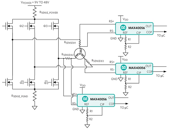
To produce efficient motor operation, the system processor has current data for all three motor phases at any given time (Figure 4).
 Figure 4: In in-line current sensing for motor control, the processor has current data for all three motor phases at any moment in time. (Image source: Analog Devices)
In Figure 4, the MCU simultaneously samples all three motor legs with Analog Devices’ MAX40056 bi-directional CSA, preserving the phase relationships between each leg’s excitation. An ideal in-line amplifier gains each motor leg's differential signal while rejecting the common-mode transients of PWM. The strong PWM rejection facilitates the fastest settling time, higher accuracy, and enables the designer to minimize the PWM duty cycle, keeping it close to 0%.
The MAX40056 is a single-supply, high-accuracy, bidirectional CSA with a high common-mode input range extending from -0.1 volts to +65 volts. The input stage provides protection against voltage spikes and inductive kickbacks from -5 volts up to +70 volts. The ±5 μV (typ) input offset voltage and 0.05% (typ) gain error help to ensure low system errors (Figure 5).
 Figure 5: The MAX40056 CSA’s ability to suppress disturbances due to fast PWM rejection circuitry makes it well-suited to in-phase current monitoring of inductive loads, such as motor windings. (Image source: Analog Devices)
In Figure 5, the input stage is specifically designed to suppress the disturbance of fast PWM signals, which are common in motor control applications. The MAX40056 is, therefore, well-suited to in-phase current monitoring of inductive loads, such as motor windings and solenoids that are driven by PWM signals. The MAX40056 operates over the full -40°C to +125°C temperature range and from a supply voltage of +2.7 volts to +5.5 volts.
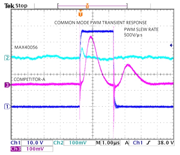
The MAX40056 has a 500 nanosecond (ns) PWM edge recovery from 500 volts/microsecond (µs) and faster PWM edges. The MAX40056 and competitor bench data illustrate a significant difference in the PWM common-mode immunity (Figure 6).
 Figure 6: A competitive comparison using a PWM edge rejection of a 50-volt PWM cycle shows the MAX40056 has a clear advantage with respect to PWM common-mode transient immunity. (Image source: Analog Devices)
In Figure 6, the MAX40056 CSA’s analog output shows a minor bump and recovers within 500 ns, while the competing device requires approximately 2 µs to recover. CSA’s patented PWM rejection input suppresses transients and provides a clean differential signal measurement.
Conclusion
Industry 4.0 and the IIoT are both emphasizing higher levels of production efficiency and reliability that must reach down to the level of individual motors. Finding suitable circuit designs to build an AC motor drive system for speed and torque to ensure stability, reliability, and energy efficiency can be complicated.
As shown, an in-line motor current sensor approach with an ideal amplifier provides true current-phase information. With this approach—and using the MAX40056 bidirectional CSA with PWM rejection—designers can configure a three-phase motor system that accurately measures torque and speed in a three-phase AC motor system, ensuring motor efficiency, reliability, and stability.

Disclaimer: The opinions, beliefs, and viewpoints expressed by the various authors and/or forum participants on this website do not necessarily reflect the opinions, beliefs, and viewpoints of DigiKey or official policies of DigiKey.


