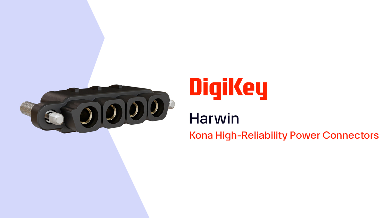
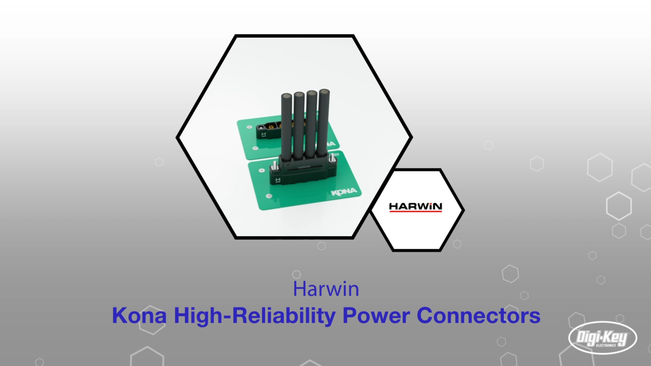
Select the Right Connector to Ensure High-Current Power Integrity in Extreme Environments
Contributed By DigiKey's North American Editors
2024-01-04
With supply voltages decreasing and load currents increasing proportionally, resistive power loss and voltage drops must be minimized for efficiency and thermal management. Power applications such as electric vehicles (EVs), aerospace, and industrial electronics also expose circuits to shock, vibration, and temperature extremes.
Designers must be aware of these requirements to ensure they select and correctly apply power connectors that are mechanically rugged, maintain electrical integrity, and operate over extended temperature ranges.
This article discusses the selection and use of power connectors for the most demanding environments and applications. It then introduces example power connectors from Harwin and shows how they can be used to achieve excellent power integrity with low losses while guaranteeing mechanical reliability.
Considerations for high-power interconnections
Connecting high current and high voltage to a printed circuit board (pc board) requires great care. Poor connections can result in power losses and unexpected electrical breakdowns. If the interconnection is also subject to extreme temperature, shock, or vibration, the problems can be multiplied. Power connectors with inadequate current ratings may force designers to use multiple contacts to obtain the required current levels, resulting in larger connectors with more contacts and additional pc board real estate. Multiple current paths also increase the chances of improper insertion, resulting in overcurrent on a single contact. The solution to these issues is to use power connectors with the correct single-contact current rating.
Consider the Harwin Kona series connectors (Figure 1). These connectors are rated to handle 60 amperes (A) per contact and up to 3000 volts AC (VAC) maximum (for 1 minute) and 1500 VAC or volts DC (VDC) peak working, even in extreme temperature, shock, and vibration environments.
 Figure 1: The Kona series power connectors handle up to 60 A per contact at 1500 VAC, and versions include header, panel mount, and cable mount. (Image source: Harwin Inc.)
The Kona connectors are available in two, three, or four-contact single-row housings. Configurations include a pc board header, a panel mount, and a male and female cable mount with various locking arrangements. They can be used in cable-to-board and cable-to-cable mating.
These connectors use contacts spaced at 8.5 millimeters (mm) (0.335 inches (in.)). This spacing, along with individually recessed contacts that are each shrouded with polarizing keyed structures, ensures the connector's high voltage and current ratings. The design also helps to protect against incidental damage due to poor mating and random physical strikes.
The secret to this connector series' high current rating and reliability is the six-fingered male contact (Figure 2).
 Figure 2: The six-fingered male contact provides positive normal spring force against the interior walls of the female contact to ensure a good connection even in the presence of shock and vibration. (Image source: Harwin Inc., modified)
The Kona series contacts are made of beryllium copper, allowing a maximum operating temperature range of -65°C to 150°C, and they are plated with a durable hard-acid gold finish for protection against long-term exposure in harsh environments. The contacts are rated for 250 mating operations, and the contact resistance of a mated pair is 2 milliohms (mΩ) or less. The voltage drop across the contact pair at the maximum rated current of 60 A is only 0.12 volts.
Headers for board mounting
The Harwin Kona KA1-MV10405M1 is an example of a four-contact vertical header intended for pc board mounting (Figure 3).
 Figure 3: The Kona KA1-MV10405M1 header has four contacts. The clearly visible identifying marker for contact 1 and the mounting studs are shown. (Image source: Harwin Inc.)
The header’s body is made of a glass-filled, high-temperature thermoplastic, and it comprises four recessed, six-fingered male contacts with a 4.5 mm (0.185 in.) pc board solder tail. A clearly visible embossed marker provides header orientation and contact 1 identification. Internal thread screw locks and board-mount studs provide a mating lock for the jack connector, as well as mechanical mounting to the pc board using a KA1-4240000 slotted board mounting nut. Headers with right-angle, horizontal mounting contacts and alternative locking arrangements are available. Make-before-lock is used to prevent the possibility of damage during the locking process.
Receptacles for cable and panel mounting
The Kona KA1-2010498F1 (Figure 4, left) is a four-contact, cable-mounted receptacle housing that uses separate contacts, such as the Harwin Kona KA1-0400005 (Figure 4, right). This housing can mate with the KA1-MV10405M1 four-contact header above.
 Figure 4: Shown are the KA1-2010498F1 four-contact receptacle housing (left) with its shroud extension and the female solder contact used with the housing (right). (Image source: Harwin Inc.)
The female cable-mounted housing includes shroud extensions with polarizing keys that prevent accidental connection with the female receptacle contacts and provide electrical isolation to the mated contacts. The Kona KA1-0400005 connector socket contact uses a solder connection to the cable. The contacts are designed for #8 AWG equipment wire. Silicone rubber insulation with a maximum diameter of 7.5 mm (0.295 in.) is recommended.
The standard gender connectors are fitted with floating thumbscrews with hex socket cavities for torque screwdrivers. Reverse fix hardware, with the locking direction flipped, has 5.2 mm long panel mount studs for front-panel mounting on an enclosure. The locking hardware is corrosion-resistant stainless steel.
Plugs for cable and panel mounting
The Kona KA1-3010498M5 (Figure 5, left) is the male cable-mounted version of the KA1-2010498F1 housing, and it uses the KA1-1410005 pin contact (Figure 5, right).
 and the solder version") Figure 5: Shown are the four-contact KA1-3010498M5 male housing (left) and the solder version of the six-fingered male contact used with the housing (right). (Image source: Harwin Inc.)
Figure 5: Shown are the four-contact KA1-3010498M5 male housing (left) and the solder version of the six-fingered male contact used with the housing (right). (Image source: Harwin Inc.)
The male or plug housing uses the solder version of the six-fingered male contact, which is designed to use the same #8 AWG wire as the female version. This model connector uses reverse fix locking thumb screws, which mate with a female connector with reverse fix hardware for panel mounting. Standard locking hardware is also available.
Small size, lightweight
The physical size of the connectors is small, given their 60 A and 3000 volt ratings (Figure 6).
 Figure 6: A dimensional drawing of Kona receptacle housings shows their small size. (Image source: Harwin Inc.)
The four contact connectors have a length (A) of 50 mm (1.97 in.), a width of 12.5 mm (0.49 in.), and a height of 18 mm (0.71 in.). A receptacle cable housing mated with a plug header has a height of 21.7 mm (0.85 in.) from the pc board. The mated pair weighs about 25 grams (g) (0.88 ounces (oz)).
Testing standards
All the Kona connector designs have been tested under the appropriate sections of EIA-364. The electrical tests include contact resistance, power, withstand voltage, and insulation resistance. The mechanical tests include shock and vibration, insertion and withdrawal forces, thermal shock, humidity, and salt spray. The vibration specification is 20 g peak for 12 hours (hr) without a contact failure. Similarly, the shock specification is 100 g for 6 milliseconds (ms) without a contact failure.
In addition to their shock and vibration tolerance, which makes the connectors suitable for EV power connections, Kona connectors meet the NASA and ESA outgassing requirements, making them ideal for space, avionic, and unmanned aerial vehicle (UAV) applications.
Shielding for interference
In applications that have limits on electromagnetic interference (EMI) and radio frequency interference (RFI), the Kona connectors offer a range of lightweight aluminum back shells for both cable and header connectors (Figure 7).
 Figure 7: For EMI/RFI protection, an aluminum back shell with flexible braiding attached to a tie band is available. (Image source: Harwin Inc.)
The back shells are designed to accommodate an abrasion-resistant, flexible metal braid and are supplied with tie-bands to secure the braiding to the shell. The combination of the back shell and braiding provides shielding for effective EMI/RFI protection. Additionally, the back shells provide additional strain relief for the cables.
Assembly tooling
The Kona connectors require a minimum of tooling. As the cable contacts are soldered, they can be inserted by pushing them in without using tools. A removal tool is available if the need arises to remove or replace a contact. A screwdriver can also be used to tighten or loosen slotted nuts on mounting studs.
Conclusion
The Kona 8.5 mm pitch, high-reliability connector family ensures power integrity in the most demanding environments. These connectors provide a quick and easy mating process that does not require additional tooling. They are ideal for avionics, UAVs, satellites, EVs, and other applications with high-power systems operating in extreme environments.
Disclaimer: The opinions, beliefs, and viewpoints expressed by the various authors and/or forum participants on this website do not necessarily reflect the opinions, beliefs, and viewpoints of DigiKey or official policies of DigiKey.