Rapidly Deploy a Battery-Powered Bluetooth 5 Certified Multi-Sensor IoT Device
Contributed By DigiKey's North American Editors
2019-11-13
Developers are being presented with a rapidly growing demand for Bluetooth-enabled portable multi-sensor designs across diverse markets; but finding effective solutions has been a challenge. Besides the fundamental requirement for ultra-low-power performance, the ability to rapidly prototype, evaluate, and customize these designs in device-to-cloud Internet of Things (IoT) applications has become essential in order to take advantage of fast-moving opportunities.
This article describes an ultra-low-power Bluetooth processor system-on-chip (SoC) from ON Semiconductor and shows how the SoC, or its associated system-in-package (SiP) version, meets fundamental requirements for battery-powered designs. An associated evaluation board and IoT development environment dramatically further simplify the process of creating multi-sensor device-to-cloud applications.
Low-power Bluetooth applications
Bluetooth-enabled battery-powered devices provide the connectivity and processing capability in smart product applications ranging from fitness wearables, medical monitors, lighting, locks, appliances, automobiles, and many more. User expectations and competitive pressures continue to drive a need for more comprehensive applications fueled by more precise data from a greater number of sensors. In some areas, such as industrial applications, multi-sensor capabilities are essential to detect movement, vibration or shock, temperature, humidity level or other data needed to ensure worker safety, equipment status, or basic asset management.
In users' day-to-day activities, these devices not only must deliver data reliably from multiple sensors but also must reduce the need to frequently replace or recharge batteries. This is critical for a satisfactory user experience. At the same time, underlying solutions need to help reduce the cost and complexity usually associated with the design of battery-powered Bluetooth products.
One such solution, the NCH-RSL10-101WC51-ABG RSL10 SoC from ON Semiconductor meets requirements for ultra-low-power operation, while also providing the hardware foundation for SiP and evaluation boards that help accelerate development of final products. Used with ON Semiconductor software for custom development, or with DigiKey’s DK IoT Studio for rapid development, RSL10-based integrated solutions let developers rapidly deploy and evaluate ultra-low-power multi-sensor applications.
Inside the RSL10 Bluetooth wireless SoC
The RSL10 is a Bluetooth 5 certified wireless SoC designed specifically to meet the growing need for ultra-low-power designs in wearables, mobile products, and other connected products (see its ULPMark score and click “Core Profile (3.0 V)” twice to sort by this parameter). With its comprehensive set of integrated subsystems and functional blocks, the RSL10 offers a single-chip solution able to meet requirements of typical Bluetooth-enabled IoT devices and wearables (Figure 1).
") Figure 1: The ON Semiconductor RSL10 SoC integrates processor and radio subsystems to provide a complete, ultra-low-power solution for Bluetooth 5 certified devices. (Image source: ON Semiconductor)
Figure 1: The ON Semiconductor RSL10 SoC integrates processor and radio subsystems to provide a complete, ultra-low-power solution for Bluetooth 5 certified devices. (Image source: ON Semiconductor)
The device's major processing blocks include an Arm® Cortex®-M3 core, a proprietary LPDSP32 32-bit dual Harvard architecture digital signal processing (DSP) core, and a complete Bluetooth 5 certified radio subsystem—all supported by dedicated and shared memory areas. To protect code and data, an IP block provides mechanisms to prevent external access to the device's on-chip flash, random-access memory (RAM), or core. Along with a full set of standard serial peripherals, the device provides a four-channel analog-to-digital converter (ADC), general-purpose IOs (GPIOs), and audio interfaces. A set of voltage regulators individually supply internal power domains, enabling the device to run off a single voltage source ranging from 1.1 volts to 3.3 volts.
In addition to being capable of supporting a variety of 802.15.4 low data rate wireless personal area network (WPAN) protocols, the RSL10 provides comprehensive support for Bluetooth through a combination of built-in hardware and software. Hardware support builds on the integrated radio frequency (RF) front-end that implements the Bluetooth physical layer (PHY). Working with the RF front end, the baseband controller provides hardware support for packet and frame processing layers of the Bluetooth protocol stack. Here, a small built-in software kernel provides event and message handling services used for RF traffic management, message exchange, and timer functionality. Finally, a Bluetooth library and associated profile libraries run on the Arm Cortex-M3 processor to complete the full Bluetooth stack for application software (Figure 2).
 Figure 2: The ON Semiconductor RSL10 SoC provides a full Bluetooth stack through a combination of software running in the Arm Cortex-M3 core and dedicated hardware including a baseband processor and underlying RF front-end. (Image source: ON Semiconductor)
Building on the hardware support in the RF front-end and baseband processor, the software stack combines lower level Bluetooth Low Energy (BLE) protocol service layers including the logical link control and adaptation protocol (L2CAP), the Attribute Protocol (ATT) and Security Manager Protocol (SMP), the Generic Access Profile (GAP) used to define connections, and the Generic Attribute Profile (GATT) used to define data exchanges based on services and characteristics.
Along with this Bluetooth protocol stack, RSL10 profile libraries support several standard Bluetooth profiles often used in wearable applications including heart rate, glucose monitoring, blood pressure, the Rezence wireless charging profile, and human interface device (HID), as well as profiles for location, running, and cycling, among others.
Efficient performance
Perhaps most important to designers, the RSL10 consumes relatively little current while providing Bluetooth connectivity at data rates ranging from 62.5 to 2000 kilobits per second (kbps). Peak receive (Rx) current with a 1.25 volt supply (VBAT) is 5.6 milliamps (mA) and only 3.0 mA with a VBAT of 3 volts. Peak transmit (Tx) current with a 1.25 volt VBAT is 8.9 mA at transmit power of 0 dBm (decibels referenced to one milliwatt) and only 4.6 mA with a 3 volt VBAT at 0 dBm transmit power.
The RSL10's energy efficiency extends through its architecture as demonstrated by its industry-leading certified EEMBC ULPMark Core Profile of 1090 (3 volts) and 1260 at 2.1 volts.
Developers can further enhance efficiency by selectively disabling hardware blocks while the RSL10 is in full run mode, or by placing the device in its low power standby or deep sleep modes during idle periods. It’s notable that the RSL10 automatically employs these power mode mechanisms to maintain a BLE connection between transceiver events. As a result, the device can perform Bluetooth advertising operations on all three Bluetooth advertising channels at 5 second (s) intervals while consuming only 1.1 microamps (mA).
Standby mode provides developers with an option for conserving power during periods of low activity lasting from hundreds of milliseconds (ms) to just a few milliseconds.
During standby mode, the RSL10 clock gates logic and memory and reduces their supply voltage to reduce leakage current, resulting in typical power consumption of only 30 mA. Because the on-chip power circuits remain active, the device can return to active operation relatively quickly.
Deep sleep mode offers multiple options to achieve significantly lower levels of power consumption while maintaining the ability to respond to external events. Operating in this mode with 8 kilobyte (Kbyte) RAM retention, the device consumes only 300 nanoamps (nA) with a 1.25 volt VBAT, or just 100 nA with a 3 volt VBAT. In the deepest sleep mode, the device consumes only 50 nA at 1.25 volts (25 nA at 3 volts VBAT) while maintaining the ability to wake in response to signals received on its dedicated WAKEUP pin.
Integrated design
The RSL10's extensive functional capabilities help developers create power-optimized designs without compromising performance or Bluetooth connectivity. Its high level of integration helps simplify hardware design. Features such as integrated capacitors eliminate the customary requirement for external capacitors with the 32 kilohertz (kHz) crystal for the real-time clock (RTC) or with the 48 megahertz (MHz) crystal oscillators for the RF front-end and main system clock. As a result, the RSL10 requires a minimal number of external components to complete a design (Figure 3).
 Figure 3: With its high level of integration, the ON Semiconductor RSL10 SoC provides a complete design with relatively few external components as shown in this configuration for operation in buck mode. (Image source: ON Semiconductor)
The device integrates multiple programmable voltage regulators for supplying digital, memory, and RF front-end blocks. A charge pump provides higher voltage levels needed for the analog blocks and flash memory. Thanks to these integrated power systems, the device can run off a single supply source of between 1.1 volts and 3.3 volts.
At voltage levels below 1.4 volts, designers can supply the device using its internal low-dropout (LDO) regulator. Above this level, the device's integrated buck converter helps enhance efficiency at the cost of an additional inductor. The circuit design for these two power source configurations differs only in that operation in LDO mode allows elimination of the additional inductor between VCC and VDC pins, shown in Figure 3. ON Semiconductor provides guidelines for component placement and physical design of printed circuit boards with the RSL10.
System design with the RSL10
For developers without the time or resources to build these hardware interfaces, ON Semiconductor's NCH-RSL10-101S51-ACG RSL10 SiP provides an effective alternative to custom hardware implementations for system designs. Measuring 6 millimeters (mm) x 8 mm x 1.5 mm, the RSL10 SiP integrates the RSL10 SoC, a radio antenna and the full set of required components in a single package. With the RSL10 SiP, designers can drop a complete ultra-low-power certified Bluetooth hardware solution into their designs and focus their efforts on their custom hardware requirements.
ON Semiconductor's RSL10 software packages similarly help focus software development efforts on custom requirements. Building on the Arm Cortex Microcontroller Software Interface Standard (CMSIS) hardware abstraction layer (HAL), the ON Semiconductor RSL10 software development kit (SDK) provides drivers, utilities and sample code distributed in the RSL10 CMSIS-Pack (Figure 4).
 Figure 4: The ON Semiconductor RSL10 software environment provides an extensive set of services and utilities in its baseline package, with additional packages providing support for Bluetooth mesh networking and Bluetooth IoT development. (Image source: ON Semiconductor)
Among its more specialized services, this pack includes Bluetooth support, the FreeRTOS real-time operating system (RTOS), and a firmware over-the-air (FOTA) update utility. In addition, ON Semiconductor provides support for more specialized functionality through separate packs for Bluetooth mesh networking and for Bluetooth IoT development (B-IDK). For example, the B-IDK CMSIS-Pack provides IoT-related services including sensor drivers, support for cloud connectivity, and related application-level software samples.
For custom development, software engineers simply load the baseline packs and optional packs into their integrated development environment (IDE). The RSL10 software distribution supports ON Semiconductor's own IDE, as well as Arm Keil µVision and IAR Embedded Workbench environments. After loading the packs, developers can explore sample applications and study implementations of key features.
BLE multi-sensor board, ready to deploy
Together, the RSL10 SiP and RSL10 SDK can jumpstart development of custom Bluetooth-enabled devices able to meet stringent requirements for ultra-low-power operation. For some applications, however, the time and resources needed to build custom solutions might not be available, or even required.
For example, industrial multi-sensor monitors or smart locks and light switches might need a small Bluetooth enabled device able to extend battery life while delivering data from multiple sensor types. For these applications, the ON Semiconductor RSL10-SENSE-GEVK multi-sensor evaluation kit can provide an immediate hardware solution. Internationally certified, the evaluation kit's board comes ready to deploy in ultra-low-power applications.
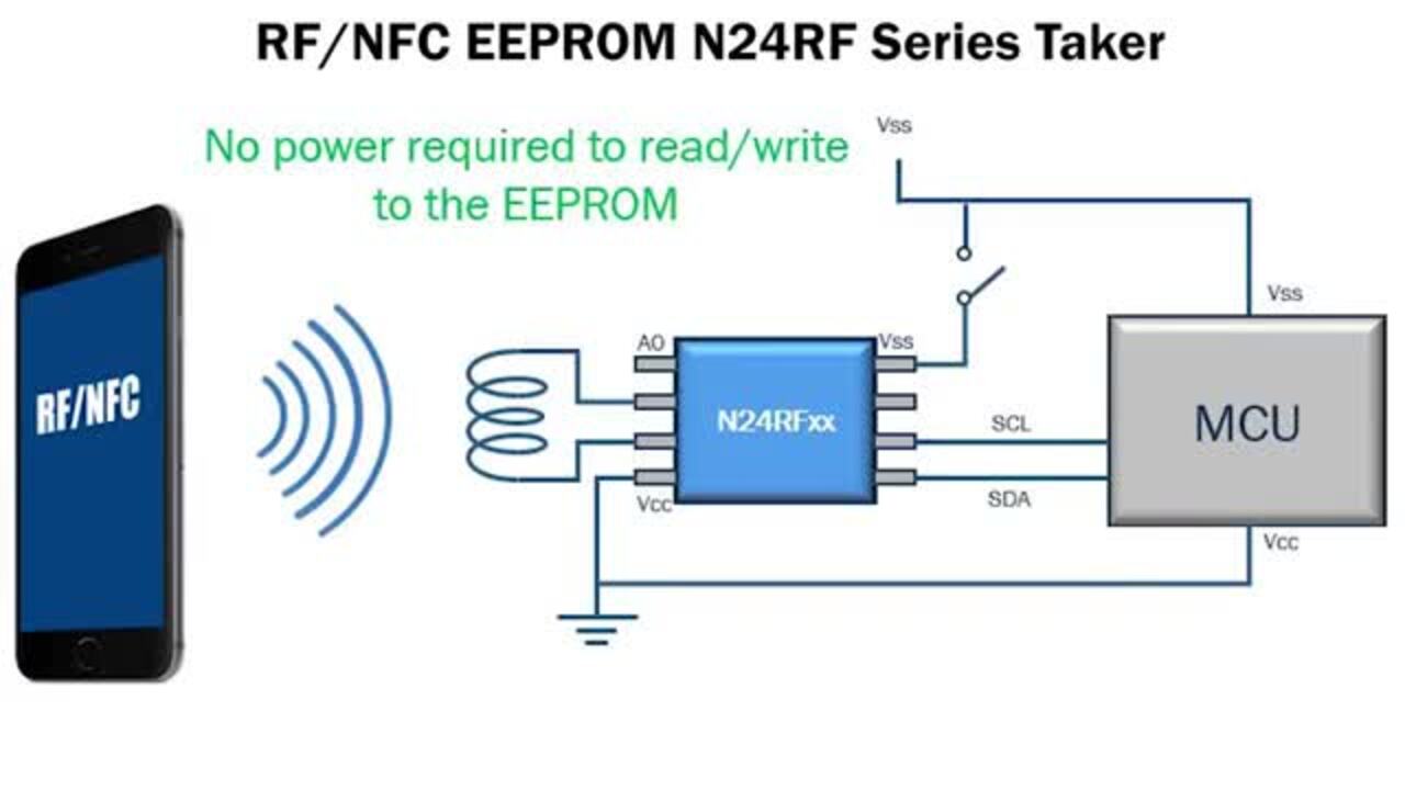
The RSL10-SENSE-GEVK board includes an RSL10 SiP, multiple sensors, an ON Semiconductor N24RF64DWPT3G 64 Kbyte near-field communications (NFC) EEPROM, an RGB LED, and programmable buttons. The board occupies a circular footprint of less than 30 mm in diameter. This is only slightly larger than the CR2032 coin cell battery and flexible NFC antenna included in the kit (Figure 5).
 Figure 5: The ON Semiconductor RSL10-SENSE-GEVK evaluation board combines an RSL10 SiP with a broad array of sensors typically required in wearables and IoT devices. (Image source: ON Semiconductor)
The board comes preloaded with firmware designed to demonstrate operation of the board's multiple sensors, including:
- Ambient light sensor (ON Semiconductor NOA1305)
- Inertial measurement unit (Bosch Sensortec BHI160) with three-axis accelerometer, three-axis gyroscope
- Three-axis digital geomagnetic sensor (Bosch Sensortec BMM150)
- Environmental sensors (Bosch Sensortec BME680) including gas, pressure, humidity, and temperature sensors
- Digital microphone
To help developers quickly evaluate sensor collection and RSL10 performance with the RSL10-SENSE-GEVK board, ON Semiconductor provides a mobile app, RSL10 Sense and Control, available through Android and iOS app stores.
Running on a Bluetooth-capable mobile device, this app allows developers to monitor power consumption with different configurations of sensors, sampling intervals and cycles, and RSL10 power mode, among other parameters. After the desired sensor configuration is set in the app, the app displays the results in a series of panes (Figure 6).
 Figure 6: The ON Semiconductor RSL10 Sense and Control mobile app provides a ready solution for evaluating multi-sensor performance of the RSL10-SENSE-GEVK evaluation board. (Image source: ON Semiconductor)
Developers can view and modify the demonstration code using the CMSIS-Pack distribution and IDE options mentioned earlier. After generating new firmware, developers need to load the image using the 10-pin needle header using an adapter, such as the Tag-Connect TC2050-IDC-NL. Although this adapter is not included in the RSL10-SENSE-GEVK multi-sensor evaluation kit, a debug version of the kit—the RSL10-SENSE-DB-GEVK—provides a soldered 10-pin debug plug and a Segger Microcontroller Systems J-Link LITE Cortex debugger for connecting to this plug.
Rapid development with DK IoT Studio
The RSL10-SENSE-GEVK multi-sensor evaluation board can eliminate hardware development for a wide array of multi-sensor applications that require extended battery life. For many of these applications, a separate online development tool from DigiKey can eliminate the need for software coding for rapid development of prototypes or even production systems. Used with the RSL10-SENSE-GEVK evaluation board, DK IoT Studio provides a no-code development approach that lets developers rapidly deploy complete sensor-to-cloud applications.
Using the DK IoT Studio graphical interface, developers drag-and-drop elements representing a wide range of hardware and software items used in IoT applications. Hardware elements range from individual GPIO pins to complete sensor devices, including those included in the RSL10-SENSE-GEVK evaluation board. Software elements range from typical low-level features like loops and conditionals used in any program, all the way to cloud service interfaces.
Using combinations of these elements, developers work in separate tabs in the DK IoT Studio graphical interface to define operations that run in the RSL10, in the companion DK IoT Studio app, and in the cloud, all without writing any software code.
This approach builds on a set of "abilities" and "events" associated with any element. For example, the BME680 integrated environmental sensor comes with a set of abilities for reading temperature, pressure, and humidity. Other functional elements, such as an interval element, come with the ability to periodically trigger events that cause execution of an element's ability. Still others represent Bluetooth communications with a Bluetooth-enabled mobile device such as a smartphone.
Building an application with this approach is straightforward, with DigiKey providing a number of demonstration projects for the RSL10-SENSE-GEVK evaluation board. For example, in a BME680 demo project an interval element triggers the BME680 sensor abilities for reading temperature, pressure, and humidity every 1000 ms. In turn, associated Bluetooth elements for each sensor output cause transmission of those sensor readings to a Bluetooth device (Figure 7).
") Figure 7: In the DigiKey DK IoT Studio device tab, developers combine elements to periodically read data from the environmental sensor on the RSL10-SENSE-GEVK evaluation board and transmit the sensor data, via a Bluetooth connection, to a companion mobile app. (Image source: DigiKey)
Figure 7: In the DigiKey DK IoT Studio device tab, developers combine elements to periodically read data from the environmental sensor on the RSL10-SENSE-GEVK evaluation board and transmit the sensor data, via a Bluetooth connection, to a companion mobile app. (Image source: DigiKey)
The application tab allows developers to build a user interface within the DigiKey mobile app for displaying the data received via Bluetooth. In the BME680 project demo, this application not only displays temperature, pressure, and humidity, but also sends each sensor reading to a cloud element (Figure 8).
") Figure 8: The DigiKey DK IoT Studio application tab provides a canvas for display of sensor data in the associated mobile app as well as a pane for generating the displayed data and performing other operations in the mobile app such as sending data to the cloud. (Image source: DigiKey)
Figure 8: The DigiKey DK IoT Studio application tab provides a canvas for display of sensor data in the associated mobile app as well as a pane for generating the displayed data and performing other operations in the mobile app such as sending data to the cloud. (Image source: DigiKey)
This use of an intermediate app to relay sensor data to a cloud application is commonly used to avoid the need for direct connections from the IoT device to the cloud. For devices with built-in Wi-Fi communications capabilities, sensor data can of course be sent directly to the cloud, and the DK IoT Studio provides Wi-Fi elements and others that support that approach. In either case, cloud operations are specified in the cloud tab. In this case, the temperature, pressure, and humidity results are stored in cloud data storage services provided with DK IoT Studio (Figure 9).
") Figure 9: In the DK IoT Studio cloud tab, developers define cloud-based operations such as storing sensor data in cloud storage. (Image source: DigiKey)
Figure 9: In the DK IoT Studio cloud tab, developers define cloud-based operations such as storing sensor data in cloud storage. (Image source: DigiKey)
After completing definition of device, application, and cloud roles, the user can compile the project in DK IoT Studio by clicking the compile icon. After code generation, the user can load the resulting firmware into the RSL10-SENSE-GEVK. Here, a small utility running on the user's system completes the transfer from the DK IoT Studio to the evaluation board connected to that system. The application and cloud code sets are automatically saved in the DK IoT Studio cloud environment.
Although this approach can eliminate the need for application code development, the events and abilities associated with each element are defined in a set of software routines, called the Embedded Element Library (EEL), that runs in the DK IoT Studio development environment.
For example, the BME680 "Read Temperature" ability invokes an abstraction bme680_get_sensor_() defined in a BME680 C-language module (Listing 1).
Copy
BME680_Status_t BME680_GetTempData( float *tempC )
{
       _BME680_StartMeasurement();

       struct bme680_field_data data;
       int8_t retval = bme680_get_sensor_data( &data, &_BME680_DriverConfig );

       if ( retval != 0 )
       {
              ATMO_PLATFORM_DebugPrint( "Error getting sensor data! %d\r\n", retval );
              *tempC = 0;
       }
       else
       {
              *tempC = data.temperature / 100.0;
       }

       _BME680_Sleep();
       return BME680_Status_Success;
}
Listing 1: Underlying the DK IoT Studio graphics interface, code associated with each element implements specific functionality, such as this function that is invoked whenever the "Read Temperature" ability is triggered. (Code source: DigiKey)
Low-level routines in the same module implement the bit manipulation operations needed to extract the desired data from sensor registers read by a lower level routine, bme680_get_regs() (Listing 2).
Copy
static int8_t read_field_data( struct bme680_field_data *data, struct bme680_dev *dev )
{
       int8_t rslt;
       uint8_t buff[BME680_FIELD_LENGTH] = { 0 };
       uint8_t gas_range;
       uint32_t adc_temp;
       uint32_t adc_pres;
       uint16_t adc_hum;
       uint16_t adc_gas_res;
       uint8_t tries = 10;

       rslt = null_ptr_check( dev );

       do
       {
              if ( rslt == BME680_OK )
              {
                     rslt = bme680_get_regs( ( ( uint8_t ) ( BME680_FIELD0_ADDR ) ), buff, ( uint16_t ) BME680_FIELD_LENGTH,
                                             dev );

                     data->status = buff[0] & BME680_NEW_DATA_MSK;
                     data->gas_index = buff[0] & BME680_GAS_INDEX_MSK;
                     data->meas_index = buff[1];

                     adc_pres = ( uint32_t ) ( ( ( uint32_t ) buff[2] * 4096 ) | ( ( uint32_t ) buff[3] * 16 )
                                               | ( ( uint32_t ) buff[4] / 16 ) );
                     adc_temp = ( uint32_t ) ( ( ( uint32_t ) buff[5] * 4096 ) | ( ( uint32_t ) buff[6] * 16 )
                                               | ( ( uint32_t ) buff[7] / 16 ) );
                     adc_hum = ( uint16_t ) ( ( ( uint32_t ) buff[8] * 256 ) | ( uint32_t ) buff[9] );
                     adc_gas_res = ( uint16_t ) ( ( uint32_t ) buff[13] * 4 | ( ( ( uint32_t ) buff[14] ) / 64 ) );
                     gas_range = buff[14] & BME680_GAS_RANGE_MSK;

                     data->status |= buff[14] & BME680_GASM_VALID_MSK;
                     data->status |= buff[14] & BME680_HEAT_STAB_MSK;

                     if ( data->status & BME680_NEW_DATA_MSK )
                     {
                           data->temperature = calc_temperature( adc_temp, dev );
                           data->pressure = calc_pressure( adc_pres, dev );
                           data->humidity = calc_humidity( adc_hum, dev );
                           data->gas_resistance = calc_gas_resistance( adc_gas_res, gas_range, dev );
                            break;
                     }

                     dev->delay_ms( BME680_POLL_PERIOD_MS );
              }

              tries--;
       }
       while ( tries );

       if ( !tries )
       {
              rslt = BME680_W_NO_NEW_DATA;
       }

       return rslt;
}
Listing 2: Code associated with each element in the DK IoT Studio translates more abstract function calls from higher level services to specific operations such as extracting data from environment sensor registers. (Code source: DigiKey)
As suggested earlier, elements provide methods like conditionals routinely used by software developers and methods like GPIO control routinely used by hardware developers. In the DK IoT Studio environment, corresponding elements provide a simple drag-and-drop approach for testing conditions and executing appropriate actions. For example, another demonstration project shows how the LED on the RSL10-SENSE-GEVK board can be turned on if the output from the board's ambient light sensor exceeds some specified value (Figure 10).
 Figure 10: The DK IoT Studio provides elements needed to perform more abstract logic such as value checking as well as low-level operations such as setting a GPIO tied to the LED on the ON Semiconductor RSL10-SENSE-GEVK evaluation board. (Image source: DigiKey)
On the cloud side, a similar test can be used to generate metadata for the mobile app. In this case, the metadata might be used in the app to set an alert icon indicating a problem detected by the sensor (Figure 11).
 Figure 11: The DK IoT Studio supports more sophisticated operations in the cloud and on the mobile app such as this condition check to set status metadata for the app and preserve the data in cloud storage. (Image source: DigiKey)
Execution of the underlying code responsible for toggling the LED follows a chain of calls starting with invocation of a higher-level function associated with that event in the underlying environment. That function, SetPinState, is a function pointer set during initialization to point to a lower level function, ATMO_ONSEMI_GPIO_SetPinState(), which implements the required functionality, ultimately calling an ON Semiconductor RSL10 SDK library function, Sys_DIO_Config(), that sets the specified pin (Listing 3).
Copy
ATMO_GPIO_Status_t ATMO_GPIO_SetPinState( ATMO_DriverInstanceHandle_t instance, ATMO_GPIO_Device_Pin_t pin,
        ATMO_GPIO_PinState_t state )
{
       if ( !( instance < numberOfGPIODriverInstance ) )
       {
              return ATMO_GPIO_Status_Invalid;
       }

       return gpioInstances[instance]->SetPinState( gpioInstancesData[instance], pin, state );
}
Listing 3: The DK IoT Studio provides a set of common abstractions that are realized in lower-level service layers, which implement hardware-specific operations such as setting GPIO bits. (Code source: DigiKey)
For all its simplicity, DK IoT Studio provides a highly flexible development environment. Developers can rely on an element's EEL code as is or modify it as required for their application. During development, the DK IoT Studio device tab provides a panel containing underlying high-level code associated with the elements placed on the tab canvas (as seen in Figure 7). For applications that require some special handling, developers can immediately modify the code in that panel. Other capabilities such as a "function" element add an empty function definition to the code, allowing developers to supplement execution with features and functions available in the environment.
In practice, the DK IoT Studio's approach combines the simplicity of no-code drag-and-drop development with flexibility and performance limited only by the amount of memory and processor capabilities of the underlying hardware devices. Using this approach with the RSL10-SENSE-GEVK board, developers can rapidly deploy fully functional prototypes with device-to-cloud connectivity and mobile app support.
Conclusion
New applications of multi-sensor devices continue to arise across diverse markets including consumer, automotive, and industrial areas. For many of these applications, Bluetooth connectivity and extended battery life are paramount, yet at the same time designers need the supporting ecosystem to also be able to respond to constant time-to-market pressure with flexible design approaches. Addressing such challenges, ON Semiconductor’s RSL10 SoC, RSL10 SiP, and RSL10-SENSE-GEVK evaluation board offer a series of solutions that fit requirements for custom design, integrated modules, and complete multi-sensor solutions, respectively. Using these hardware platforms, developers can implement custom applications using the RSL10 software development kit and associated software distribution packs.
For fast development of multi-sensor device-to-cloud applications, the combination of the ON Semiconductor RSL10-SENSE-GEVK evaluation board and DK IoT Studio IDE provides a powerful rapid development platform for implementing ultra-low-power multi-sensor solutions in complete device-to-cloud applications. Together, RSL10 hardware and available software options provide a highly flexible platform for development and deployment of certified Bluetooth devices able to meet demand for extended battery life.
Disclaimer: The opinions, beliefs, and viewpoints expressed by the various authors and/or forum participants on this website do not necessarily reflect the opinions, beliefs, and viewpoints of DigiKey or official policies of DigiKey.