Multilayer Ceramic Capacitors (MLCCs)
Contributed By DigiKey
2018-01-25
Introduction
This document will cover the basics of multilayer ceramic capacitors, the proper procedure to test them, and a description of the aging/de-aging process.
Description
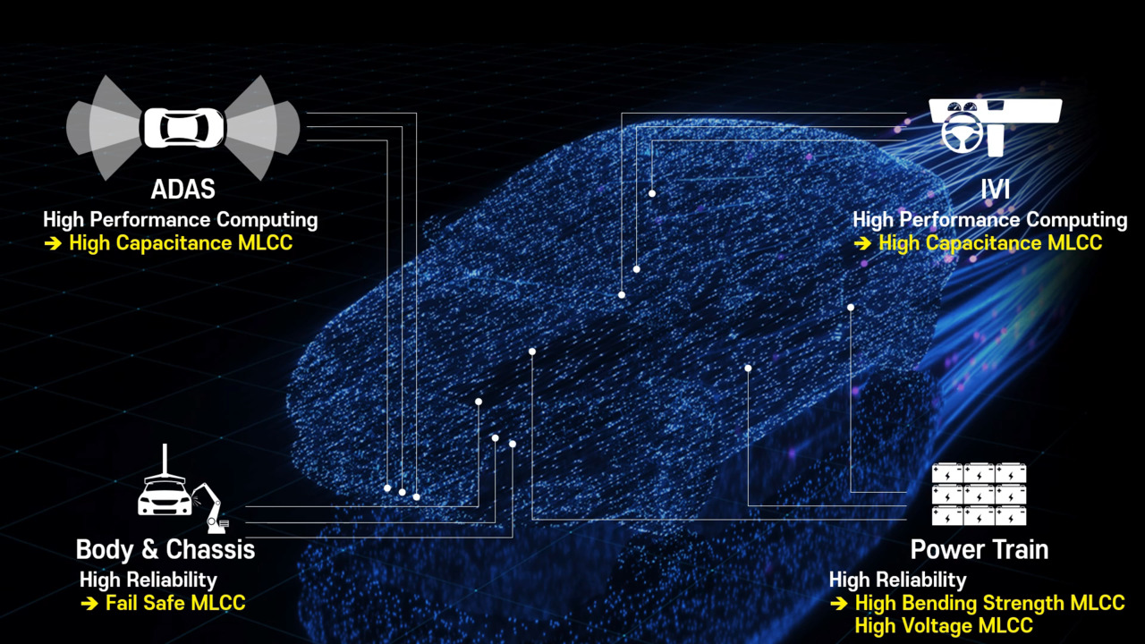
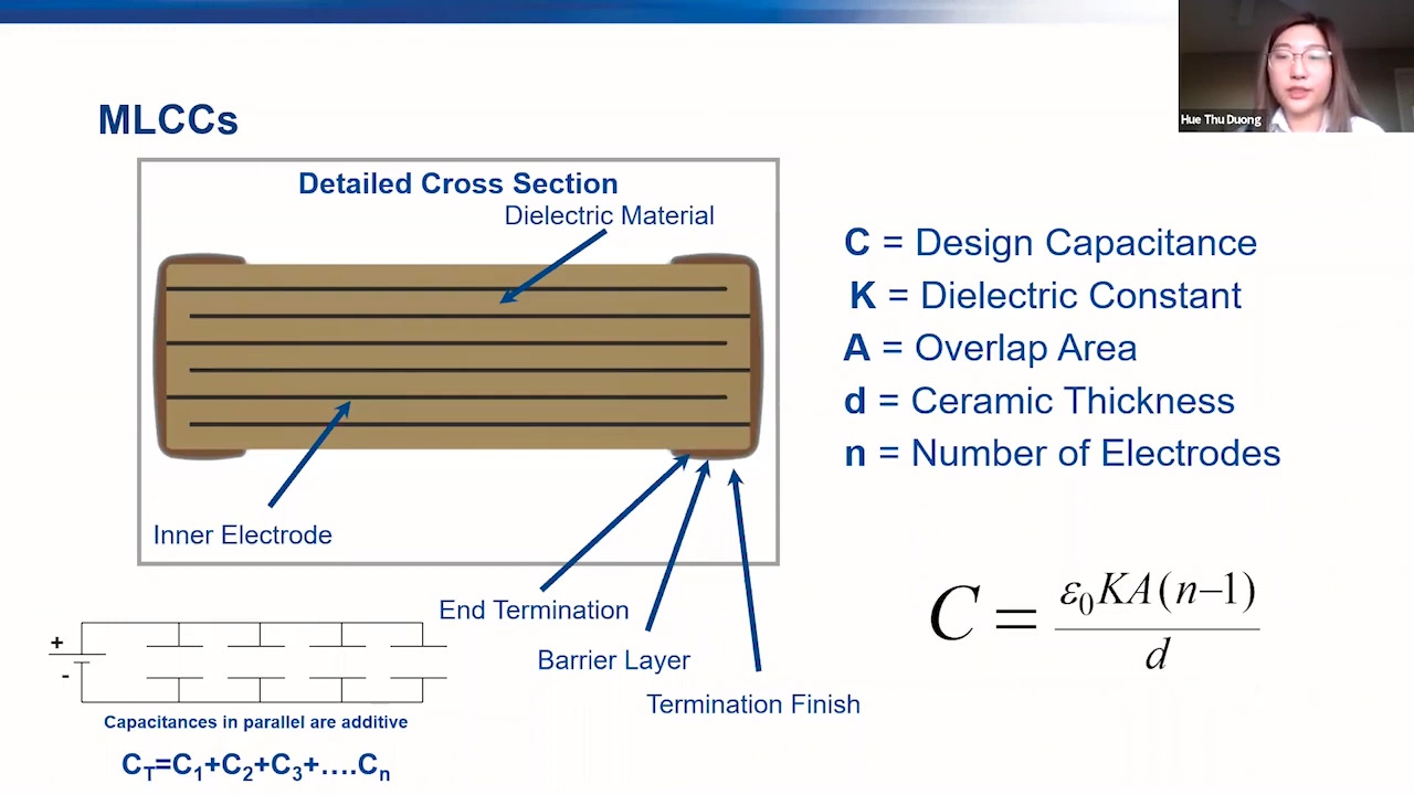
MLCC (multilayer ceramic capacitors) are the most prevalent capacitors utilized in the electronics industry. Class I ceramic capacitors (ex. NP0, C0G) offer high stability and low losses in resonant circuits, but low volumetric efficiency. These do not require any aging corrections. Class II and Class III (X7R, X5R, etc.) offer high volumetric efficiency, but a lower stability than Class I dielectrics. These can sometimes require aging correction if they are outside of the manufacturer’s referee time. The referee time is the timeframe the manufacturer deems the capacitor to be within the specified tolerance range.

Figure 1:Typical MLCC
Testing
Most LCR meters are unable to test high value (1 µF and higher) MLCCs due to their internal impedance. The impedance is so low at 1 KHz that it virtually drains the current supplied by the meter, ultimately dropping the specified voltage to 0, never allowing the capacitor to be exposed to the required voltage for testing. To verify, measure the voltage across a capacitor under test with a true RMS meter. If the voltage is less than 0.4 VRMS, the capacitance reading will be low. Select LCR meters have an impedance matching capability function called Automatic Level Control (ALC). These meters will decrease their own impedance until it’s lower than the device being tested. More often than not, this is still not enough and an amplifier unit is necessary to increase the current through the capacitor until the voltage across it reaches a pre-set level from 0.5 VRMS-1 VRMS.
Aging
Capacitors classified as having a high dielectric constant will decrease in capacitance over time. This is typically noted as a percentage drop per decade of time. Temperature compensating capacitors (Class I) don’t have aging characteristics.
De-Aging
If aging has affected a capacitor, it can be reversed by heating it above its Curie temperature. The Curie temperature for most manufacturer specifications is approximately 125°C or higher, and is often achieved during the soldering process. Be sure to check the manufacturer’s specs before attempting this. Heating the capacitor above the Curie temperature will realign the molecular structure of the dielectric material, restoring the MLCCs capacitance. The capacitance will often measure high at this point, and one should wait until the referee time has passed so the capacitor will be within the spec tolerance again. After the capacitor has cooled, the aging process will restart.
References
Disclaimer: The opinions, beliefs, and viewpoints expressed by the various authors and/or forum participants on this website do not necessarily reflect the opinions, beliefs, and viewpoints of DigiKey or official policies of DigiKey.