M12 Connectors Versus the Alternatives in Industrial Applications
Contributed By DigiKey's North American Editors
2021-01-14
M12 connectors are a ubiquitous round cable-termination option used extensively in industrial, mobile robot, and even consumer-grade designs to connect sensing, actuating, and other components (fieldbus and otherwise) to controls and other systems in automated machinery. The exact geometries and conductor arrangements of M12 connectors (often on the ends of PUR-jacketed or PVC-jacketed cable) are defined by the International Electrotechnical Commission’s IEC 61076-2-101 standards. The M12 name originates from how the metric thread on most of the connectors’ coupling nuts and mating receptacles (described in more detail shortly) are essentially 12-mm-diameter fasteners with an M12 thread.
Dozens of specialized options let design engineers specify corsets that are particularly well-suited to the machine or product design. Options include those with:
- Right-angle and straight bodies
- Male and (far more common) female wire-side fastener geometry
- Shielded and unshielded internals
- Fully integrated cord set as well as modular versions
- Lightweight and armored versions
- Various coupling-nut designs and constructions
Shielded M12 QUICKON (IDC) connectors are a type of M12 connector that lets installers field-wire their machine’s connections. (Video source: Phoenix Contact)
Review of the M12 standard
M12 connectors were first released in 1982 as a non-standardized 7⁄8 in. three-pin connector for a handful of applications. The unique feature of the connector was (and in most cases still is) its coupling nut — a housing on the cable end axially locked onto the cable end but allowed to freely spin – and therefore able to screw onto the matching male or female fastener geometry on the receptacle side. First the connector was standardized by IEC 61076-2-101 for use with sensors and actuators. Then over subsequent years the standard expanded to define several M12 codes (detailing pin geometry and function variations) as well as two smaller formats for use with actuators as well as PLCs, switches, and I/O. These include M8 connectors (defined by IEC 61076-2-104 and having an 8-mm fastener diameter) as well as M5 connectors (defined by IEC 61076-2-105 and having a 5-mm fastener diameter).
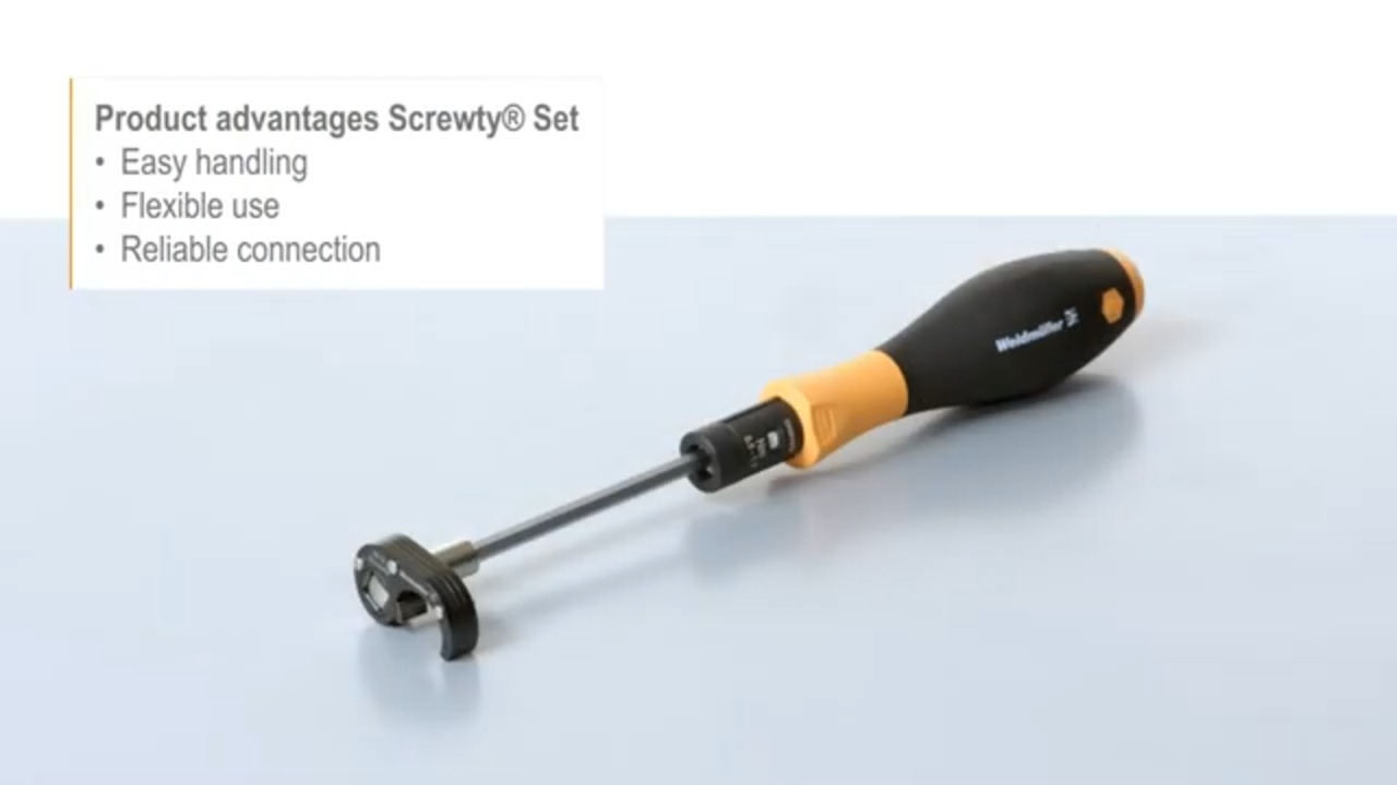
 Figure 1: Standardization of M12 and M8 connector geometry imparts many benefits — including the availability of tools to speed installation. Case in point: Screwty ratcheting drivers accommodate a conventional 1/4-in. adapter through which the installer can quickly tighten down connectors — including round plug-in M12 and M8 connectors as well as customizable M12F, M8F, and M23 plugs and sockets. (Image source: Weidmüller)
The latest iteration of IEC 61076-2-010 (2020) contains one of the biggest additions to the standard in quite some time — the addition of support and official definitions of push-pull connections. Cable companies involved in the standard’s development include Molex, CONEC, Weidmüller, Phoenix Contact, and HARTING. The main strengths of push-pull M12 connections are:
- How they dramatically reduce assembly time (by eliminating the need for screwing down nuts and verifying the applied torque)
- How they make connections that are more compact than traditional M12 connectors.
 Figure 2: M12 PushPull connectors click into place to join upright sockets as well as recessed sockets. The 2020 edition of IEC 61076-2-010 defines a push-pull M12 standard intended to magnify the successful application of push-pull M12 connectors, which are already on the market in proprietary formats. (Image source: HARTING)
In fact, IEC 61076-2-010 2020 defines the geometries of both the inner locking subcomponents on the female push-pull connector half and the outer locking subcomponents on the male push-pull connector half. That ensures cross-compatibility between cable products.
Another connector option
Not to be confused with the M12 push-pull option is another round connector that’s used in communications and industrial HMI peripherals — the miniature-DIN connector. Here, DIN stands for the Deutsches Institut für Normung — the governing standards organization that defines the structure and connections within these cable terminals. They rely on an interference fit (friction) between a sleeve on the cable end to stay plugged into the receptacle upon assembly. These 9.5 mm (3/8 in.) mini-DIN connectors come with pin arrays having three, four, five, six, seven, eight, or nine electrical connectors arranged to prevent accidental misconnections with visually similar mini-DIN cables. In many instances, suppliers will add proprietary color coding to the cable end and machine -side receptacle to help the assembler align the two connection halves and make installation somewhat more straightforward.
Both mini-DIN and M12 connectors have distinct applications for which they excel. However, there are more nonstandard mini-DIN connectors on the market — which can allow for more design freedom as well as confusion. In addition, the interference fit of the mini-DIN securement sleeve allows for quick connection and disconnection. In contrast, the screw attachment of M12 connectors does take a bit more time to join but is inherently more secure.
M12 pin counts and coded variations
 Figure 3: M12 connectors come in various pin counts and coded pin assignments. In some sets, a coupling nut (axially trapped on the cable end) screws down on the male component-side receptacle. Originally, M12 connectors had three or four pins; now they’re available with five, six, eight, or 12 pins. (Image source: EE World)
Besides pin counts, M12 connectors are also standardized on code versions. This defines the pin array, channels and notches to prevent improper mating, and electromagnetic shield design.
A-coded M12 connectors abound and are still used to network sensors and other small devices that run off dc power. B-coded M12 connectors are common in PROFIBUS installations. C-coded dual keyway (M12 Power) connectors excel in designs requiring the supply of ac power to small automation components. D-coded M12 connectors support 100 Mb/sec Ethernet as well as PROFINET connectivity.
Newer M12 code versions include K-coded and L-coded connectors supporting the supply of ac and dc power, respectively. Similar options are S-coded connectors (capable of supplying up to 690 V to for running ac motors) and T-coded M12 connectors for dc power. However, X-coded M12 connectors have seen the most dramatic rise in use to support 10 Gb/sec industrial Ethernet as well as power supply to actuators such as step motors leveraging Power over Ethernet 802.3at (PoE+) connectivity. The latter provides enough wattage to run various actuators at full power.
Conclusion
Gone are the days when the cabling and physical networking of automated machines relied on hand twisting, insulating, and testing of bare wires through conduits that took electricians hundreds of hours to install. Today’s M12 connectors (along with other innovations in cabling as well as a burgeoning array of specialized cordsets) can often eliminate the need for specialized technicians to execute an install even while allowing for quick, safe, and fault-free setup that’s easy to replace if needed. In fact, M12 connectors are part of a larger trend in machine and factory automation towards simple, modular, and non-proprietary solutions.
Disclaimer: The opinions, beliefs, and viewpoints expressed by the various authors and/or forum participants on this website do not necessarily reflect the opinions, beliefs, and viewpoints of DigiKey or official policies of DigiKey.