Improve Factory Safety and Productivity by Quickly Adding Machine Vision to Industrial Systems
Contributed By DigiKey's North American Editors
2020-10-06
Designers of machines in industrial automation are being required to implement some form of machine vision to determine the distance from all objects in a specific field of view. The reasons for implementing this form of machine vision for ranging can vary, including sensing the general environment for changes or intrusions, the ranging of objects on a production line, or overall operator or robot protection from hazards. In particular, indoor vehicles in industrial warehouses are implementing machine vision for automated driving, object location and identification, and obstacle detection and avoidance.
The most common method of indoor machine vision for object distance detection is light detection and ranging (LiDAR) which uses laser light to measure the distance between objects. LiDAR measures the return time and wavelength of the reflected laser light to determine the distance from each point. However, LiDAR machine vision algorithms are very complex and have a steep learning curve, requiring experts in machine vision to code the application.
This article will show developers how to use a turnkey LiDAR camera from Intel for these applications to detect the distance from objects in the field of view. It solves the problem of quickly adding machine vision to new or existing systems without learning the complexities of machine vision technology and algorithms. It will then show how to pair the Intel LiDAR camera with a single-board computer (SBC) from UDOO using a high-speed USB 3.1 connection.
Machine vision in indoor industrial automation environments
Industrial automation indoor environments are becoming increasingly dynamic with more equipment being added to the floor, as well as additional operators and supplies. All the machines, sensors, and increased levels of automation are meant to increase efficiency while ensuring operator safety.
In many cases the additional sensors are meant to detect objects, including people, in a target area. An object on a production line can be detected in many ways, including a basic light sensor that detects a change in ambient light due to an object passing, a mechanical switch that’s depressed by the weight of the object, or a beam of light across a production line that is interrupted when a product rolls past. While these methods are appropriate for basic object detection, increased sophistication in automation has required more complex visual detection similar to the human eye.
Machine vision is roughly analogous to adding eyesight to machines to identify different colors, differentiate objects from one another, and recognize multiple movements. However, a common and highly practical type of machine vision is to detect the distance of all objects in a field of view.
There are two common methods for performing distance detection for multiple objects. The first is radar, which for an indoor environment has the immediate concern of being hazardous to human operators under constant exposure to high-frequency signals. In outdoor environments, radar frequencies bounce off objects before dissipating harmlessly into the surrounding environment. When used indoors, radar will repeatedly bounce off multiple objects, resulting in intense levels of electro-magnetic interference (EMI). Prolonged exposure can have long term health effects on human operators.
The second common method for performing distance detection of multiple objects in a field of view is laser light ranging, also referred to as LiDAR. One or more laser light beams are directed at the objects whose distance is to be measured. The time it takes for the laser beam to reflect back to a receptor at its origin point, along with any phase shift of the beam, is compared against the time and phase of the emitted laser. An algorithm calculates the distance to the objects based on time and phase difference and converts it to centimeters or inches.
The calculation of time and phase difference for a single laser beam to detect one object is fairly straightforward. However, a more complex machine vision application would involve calculating the distance of dozens of objects in a field of view. Combining those calculations to create a visual map of the distances is not trivial and can take extensive development time.
Machine vision with distance detection
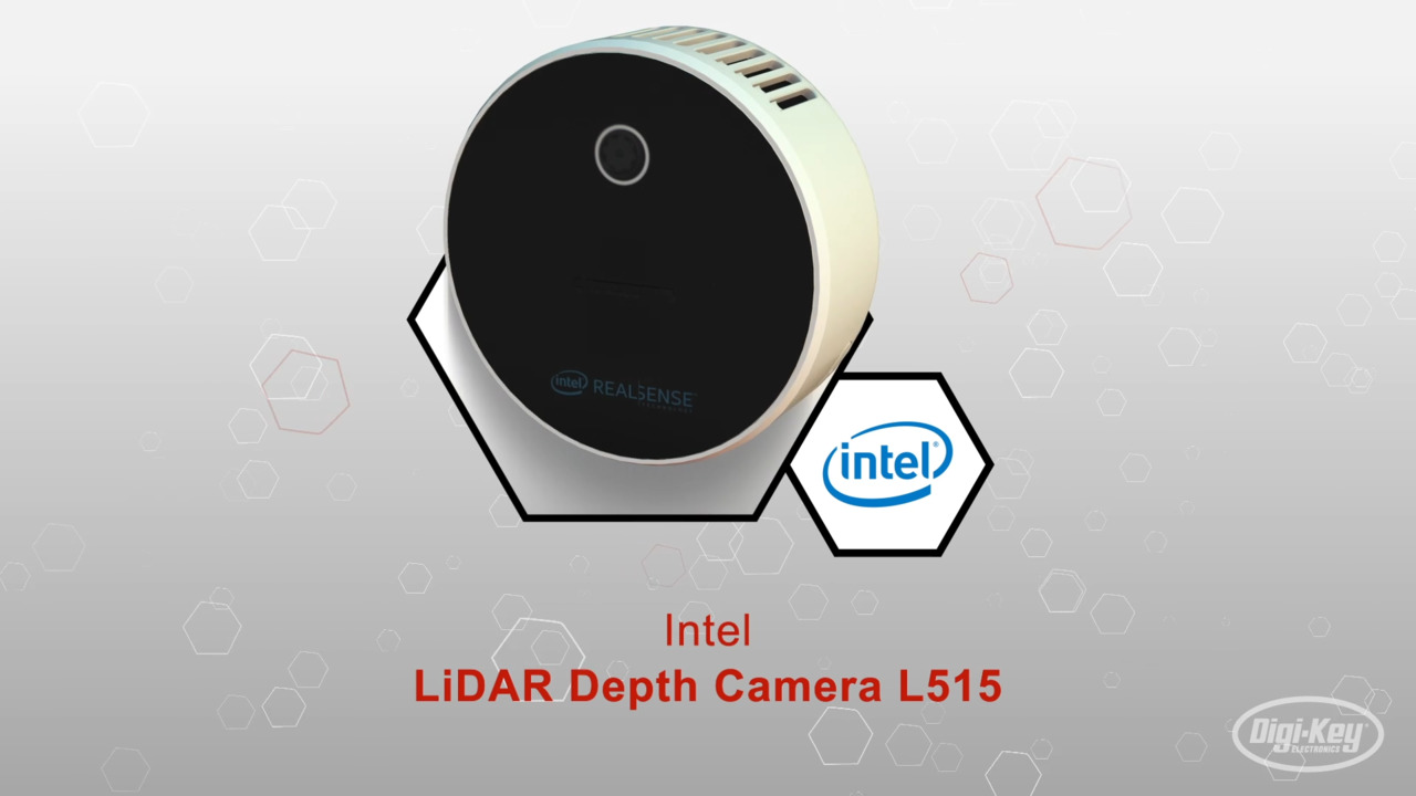
A practical solution for a machine vision application that can get up and running quickly is the Intel RealSense 82638L515G1PRQ high-resolution L515 LiDAR depth camera (Figure 1). The camera is 61 millimeters (mm) in diameter and 26 mm in depth, and contains a LiDAR image depth unit, red, green, blue (RGB) camera, and an inertial measurement unit (IMU). The LiDAR camera can return a 1024 x 768 or a 1920 x 1080 image bitmap with each pixel representing the distance that point is from the camera.
 Figure 1: The Intel RealSense L515 is a self-contained, high-resolution LiDAR camera which also has an RGB camera and IMU. It easily connects to a supporting computer using USB 3.1. (Image source: Intel)
The Intel L515 LiDAR camera returns a bitmap image of the area in its visual field. However, instead of returning a typical photographic image of the area, the LiDAR camera returns an image where the RGB value of each pixel represents the distance each pixel is from the Intel L515 camera. The camera has a resolution of from 0.25 to 9 meters. It also contains a standard 2 megapixel (MP) RGB image camera which is useful during development. It is recommended for indoor lighting situations as it was not designed to operate where there is plenty of sunlight.
An example image from the Intel L515 is shown in Figure 2. The camera image is centered on a plant in the foreground and is divided into two sections. The left side shows a regular RGB camera image of the plant and background in natural colors. The right side is a visual representation of the distance each object is from the camera. The plant in the foreground displays as shades of blue, while the wall in the background shows bright orange. To the right, the wall is further away from the camera center, so the image becomes deeper shades of red.
 Figure 2: The Intel L515 LiDAR camera returns both an RGB image (left), and a bitmap image (right) that represents the distance an object is from the camera. Closer to the camera shows up as blue, while further away shows up as deep red. (Image source: Intel)
Using this information, software can process the image data to determine the distance between objects and the camera.
With its compact size and high level of integration, the Intel L515 LiDAR camera is appropriate for indoor industrial automation applications where machine vision depth sensing must be quickly implemented into new or existing systems. For mobile systems, the Intel L515 contains an IMU that can sense ±4 g of acceleration and a gyroscope that can sense up to ±1000˚per second (˚/s) of rotation. This is appropriate for most indoor vehicles or robots used in industrial automation facilities. Care must be taken when coding firmware for the IMU as a vehicle or robot that hits an obstacle can momentarily see more than 4 gs, an exception that must be accounted for.
Machine vision in a complete system
The Intel L515 can interface to a PC or single board computer (SBC) using a high-speed USB 3.1 interface. The camera housing has a USB Type-C® connector, so standard cables with Type C connectors can be used for ease of integration. As machine vision image processing can be CPU intensive, it’s recommended to have plenty of performance so that image data sets can be processed in real-time if needed. The UDOO KTMX-UDOOBL-V8G.00 Bolt V8 is a high-performance SBC based on a four-core processor running at 2.0 gigahertz (GHz) (with a 3.6 GHz boost) and supported by up to 32 gigabytes (Gbytes) of DRAM. For program memory it can use an M.2 solid state drive (SSD) and also supports a standard SATA-3 hard drive interface.
 Figure 3: The UDOO Bolt V8 is a powerful SBC with a four-core processor running at up to 3.6 GHz. It supports M.2 and SATA-3 external drive interfaces, has room for up to 32 Gbytes of DRAM, and has a USB 3.1 Type C connector for interfacing to the Intel RealSense L515 LiDAR camera. (Image source: ODOO)
The UDOO Bolt V8 has two HDMI 1.4 video interfaces for connecting to a monitor. For networking it can interface to a factory network by wired Gigabit Ethernet via an onboard RJ-45 connector. Wi-Fi and Bluetooth are also supported. Stereo audio is supported through a 3.5 mm standard plug. The SBC will run any 64-bit x86 compatible operating system including Microsoft Windows and any 64-bit Linux distribution. This powerful SBC requires a 19 volt, 65 watt power supply to support 2 GHz of performance.
For machine vision data algorithms, the UDOO Bolt V8 has plenty of processing power. It can take in data from the Intel RealSense L515 through a high-speed USB 3.1 Type C interface, and if necessary, can display the image on a monitor connected to either of the HDMI interfaces. Audible alerts or warnings can be sounded by speakers connected to either of the audio output jacks.
Conclusion
Machine vision with depth sensing is a rapidly expanding field that can require complex code and hardware if built from scratch. Incorporating a machine vision system using turnkey solutions that perform the depth calculations in pre-programmed firmware saves time and money, resulting in a high-performance machine vision system that can be put to work in an industrial automation environment quickly and reliably.
Disclaimer: The opinions, beliefs, and viewpoints expressed by the various authors and/or forum participants on this website do not necessarily reflect the opinions, beliefs, and viewpoints of DigiKey or official policies of DigiKey.