How to Use AC Isolation Transformers in Medical Equipment to Prevent Shock
Contributed By DigiKey's North American Editors
2020-12-03
As the use of electrical medical equipment expands, from hospitals and hospices to home-based monitoring and life support, so too has concern over operator and patient safety. While there are stringent design rules based on good design practice and multiple safety standards to prevent dangerous or even lethal shock from the line voltage, it can still happen. All it takes is for a fault in the instrument to cause its enclosure or external probes to become “live,” placing the user or patient in a fault-current path to ground. With a properly selected and placed transformer, this can be avoided.
Transformers of course have many uses, from stepping alternating current (AC) voltages up or down or breaking ground loops of sensitive transducer interfaces, to impedance matching, interstage coupling, and implementing transformations between single-ended and balanced circuits. They are also used at a 1:1 turns ratio to provide galvanic isolation between the AC line and a load. This last function is increasingly important and relevant in the context of protecting operators and patients from medical equipment design faults.
This article will look at the nature of the possible fault modes and the use of a transformer for AC line isolation and thus, safety in line-powered medical instruments. Using representative units from BEL Signal Transformer, it will identify some of the relevant standards along with factors which must be considered to ensure the transformer provides the type and level of isolation needed. It will also factor in compatibility with modern assembly and production flows.
How do electrical shocks happen?
To understand the shock risk, it is useful to return to the first principles of electricity. The user is at risk if current, driven by the potential of the AC line, flows through the body and back to its source. However, if that current has no return flow path, then there is no risk, even if the person is touching a high-voltage line.
A single-phase AC line has three wires: line (L), neutral (N), and ground, where ground is a true Earth connection and normally carries no current. In standard house wiring the ground wire is not insulated and is left bare and exposed. Unfortunately, the term “ground” is very often misused in electronic circuit schematics and discussions. “Earth ground” is not the same as “chassis ground” or “common” (signal ground), and there is a different symbol for each (Figure 1).
 Figure 1: The term “ground” (left) for true Earth ground is often misused and conflated with chassis ground (right) or common (signal ground) (middle), and there are distinctly different symbols for each. (Image source: Autodesk)
The role of the isolation transformer is to allow the AC voltage to reach the operating product and its circuit (the load) while preventing flow of current through the user and back to the neutral line. This cannot happen because the isolation transformer does not have a wire from neutral to Earth, so the current will not flow through the user. The isolation transformer may even have a 1:1 turns ratio so its input and output have the same voltage. In addition, units are also available which step-down the secondary-side voltage which often simplifies conversion, rectification, and regulation of the circuit’s power rails.
It’s the current that kills
People normally associate shock risk with higher voltages. This is a valid correlation but only in an indirect way. What causes shock – whether at or below a lethal level – is current flow through the body. This current flow, in turn, is due to a voltage which drives (forces) the current into and through the body. This relationship is made clear by the term “electromotive force” (EMF), which was very commonly used for voltage in earlier days (and still is in some cases).
It’s important to keep two circuit fundamentals in mind:
- Voltage is not defined at a single point; it is defined and measured between two specific points. A better name for voltage is “potential difference”.
- Potential difference causes current to flow. The amount of current depends on the resistance between the two points and is characterized by Ohm’s Law. The larger the potential difference, the greater the current flow and the greater the risk it poses.
What about risk from battery-operated devices with no AC line connection? These devices do not pose a shock hazard, even with high-voltage batteries (unless the user grabs one battery terminal with one hand and the other terminal with the other hand). If the case gets connected to one of the battery terminals and thus to the user, there is still no current path from the user back to the other battery terminal.
There are also line-operated power tools which do not have safety grounds, yet don’t need isolation transformers: how is this possible? Until a few decades ago, construction tools such as drills had metal cases. If there was an internal fault which made the case become “live”, the current path could be through the user. To prevent this situation, the metal case was connected to the ground terminal of the unit’s AC cord. However, this was always a risky solution, as in many real-world scenarios the ground wire of the cord was not really connected to Earth ground due to a faulty cord, outlet, or use of a “cheat” three-wire-to-two-wire adapter for non-grounded outlets.
The solution which is now widely used is a “double-insulated” design. The tool’s internal electrical circuits are insulated as usual, and the case is also non-conductive with no exposed conductive parts. In this way, even if there is an internal fault and short circuit to the case—or a drill bit hits a live AC wire in a wall—the user is still protected from current flow. Double-insulated tools meet the standards of the National Electrical Code (NEC) and are preferred because they don’t rely on an often-absent grounding connection in a three-wire plug. In fact, double-insulated tools and instruments only have a two-wire plug for Hot and Neutral connections.
Even small currents are risky
An obvious question is: what are the maximum levels of current which are dangerous or even lethal, and affect human safety? This is a question which has multiple answers, depending on where the current is applied to the body and what detrimental effect is being considered.
A standard line voltage (110/230 volts; 50 or 60 hertz (Hz)) across the chest even for a fraction of a second may induce ventricular fibrillation at currents as low as 30 milliamperes (mA). Note that danger levels for DC are much higher at around 500 mA, but this discussion concerns AC and isolation. If the current has a direct pathway to the heart such as via a cardiac catheter or other kind of electrode, a much lower current of less than 1 mA (AC or DC) can cause fibrillation.
These are some standard thresholds which are often cited for current through the body via skin contact:
- 1 mA: Barely perceptible
- 16 mA: Maximum current an average-size person can grasp and “let go”
- 20 mA: Paralysis of respiratory muscles
- 100 mA: Ventricular fibrillation threshold
- 2 amperes (A): Cardiac standstill and internal organ damage
The levels are also a function of the current flow path, meaning where the two points of contact with the body are located such as across or through the chest, from an arm down to the feet, or across the head.
Safety maximums are stringent
The amount of current flow is a function of skin resistance and body mass. Guidelines from The National Institute for Occupational Safety and Health (NIOSH) state, "Under dry conditions, the resistance offered by the human body may be as high as 100,000 ohms (Ω). Wet or broken skin may drop the body's resistance to 1,000 Ω," adding that "high-voltage electrical energy quickly breaks down human skin, reducing the human body's resistance to 500 Ω." Ohm’s Law (I = V/R) quantifies the rest of the current flow situation.
Of course, safety margin prudence requires that the maximum allowed currents be far lower than the numbers cited. This is a complicated subject covered by an array of overlapping standards, many of which are now “harmonized” across international boundaries. The standards cover factors such as allowable leakage current, dielectric strength, and creepage and clearance dimensions.
What’s the difference between a medical device rated isolation transformer and a standard AC power transformer? After all, they both use primary and secondary windings on a magnetic core to achieve 1:1 or other conversion ratios. The difference is that a conventional transformer does not have to meet all of the above regulatory mandates or needs to meet them but only to a much less stringent degree.
There is no single number that can be assigned to each parameter, as their maximum values are a function of many factors. They are also defined by whether the overall design uses single or dual Means of Protection (MOP) and whether that MOP is a Means of Patient Protection (MOPP) or Means of Operator Protection (MOOP).
Among the many relevant standards are:
- IEC 60950-1:2001, “Information technology equipment - Safety - Part 1: General requirements”
- IEC 60601-1-11:2015, “Medical electrical equipment — Part 1-11: General requirements for basic safety and essential performance — Collateral standard: Requirements for medical electrical equipment and medical electrical systems used in the home healthcare environment”
- ISO 14971:2019, “Medical devices — Application of risk management to medical devices”
Describing these standards and their many mandates and test conditions in detail is far beyond the scope of this article. However, there are two project development tactics that will accelerate the efforts of designers developing a system which meets the medical isolation regulatory requirements:
- Work with a component vendor who credibly demonstrates that they have the expertise and competence that enables them to understand, implement, and meet these requirements and the many standards which define them. Designers shouldn’t try to figure it all out themselves as it can be very time-consuming.
- To the extent possible, use individual components—such as transformers—that are compliant with relevant standards as part of a building block strategy. The less attractive option is to do the design using non-compliant components, then add whatever is needed “around them” to comply, but this is often complex and costly.
These standards place multiple requirements on isolation transformer performance which then affect the overall product, such as:
- Dielectric rating and high-potential (hi-pot) test, which characterizes insulation integrity and breakdown voltage within and between windings; this is usually done on the order of several kilovolts.
- Creepage (the shortest surface distance between two conductive parts) and clearance (the shortest distance through air between two conductive parts) to avoid high-voltage flashover; these distances are specified as a function of the transformer voltage rating.
- Leakage current, the amount of current that leaks from windings to core and from winding to winding when voltage is applied to the transformer; must generally be on the order of 30 microamps (µA) or less.
- Leakage currents due to intra and inter-stage capacitance, which is a function of transformer design, core, and windings, which also must be in the 30 µA or less range (Figure 2).
- Flammability rating, such as but not limited to UL 94V-0, evaluates both the burning and afterglow times after repeated flame application and dripping of the burning test specimen in a vertical burning test.
 Figure 2: The simplest transformer model shows windings and core only, but a better model adds the various capacitances C1, C2, and C3 which enable leakage current between electrically insulated sections. (Image source: Voltech Instruments, Inc.)
The tests for meeting the standards are done following detailed conditions prescribed by the standards, often while or after stressing the transformer electrically and thermally at elevated voltages and temperatures, respectively, to assess performance during and after worst-case conditions.
Available isolation transformers illustrate diverse capabilities
A good way to better understand how isolation transformers address the various needs of systems designers is to look at some models as examples. We’ll highlight four representative units from Bel Signal Transformer with different features and capabilities, all designed to provide isolation, meet regulatory requirements, and integrate with assembly and production needs.
1: The M4L-1-3 is a 300 volt-ampere (VA), chassis-mount unit in the Signal Transformer More-4-Less family with a dielectric strength rating of 4 kilovolts (kV) (Figure 3).
 Figure 3: The M4L-1-3 power transformer features 12 mm creepage distance between the input and output windings, leakage current below 30 µA, and “finger-safe” terminals. (Image source: Signal Transformer)
The M4L-1-3’s multi-tap primary allows it to handle input voltages of 105, 115, and 125 VAC (50/60 Hz) while delivering 115 VAC on the secondary side (Figure 4). The design features 12 (mm) creepage distance between the input and output windings along with leakage current below 30 µA. Physical connection considerations include IP20 type “Touch-Safe” terminals (cannot be touched by fingers and objects greater than 12 mm) with a screw/binding clamp for hard wiring, and 3/16” & 1/4” Fast-On connections.
") Figure 4: The M4L-1-3 accepts input voltages of 105, 115, and 125 VAC (50/60 Hz) while delivering 115 VAC on the secondary side. (Image source: Signal Transformer)
Figure 4: The M4L-1-3 accepts input voltages of 105, 115, and 125 VAC (50/60 Hz) while delivering 115 VAC on the secondary side. (Image source: Signal Transformer)
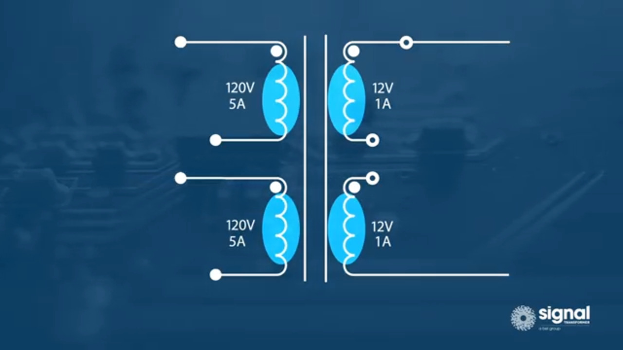
2: The 14A-30-512 from the One-4-All series is a 30 VA, through-hole mount unit with a 4 kV dielectric rating (Figure 5).
 Figure 5: The 14A-30-512 series is a 30 VA, through-hole mount unit with a 4 kV dielectric rating. (Image source: Signal Transformer)
The 14A-30-512 takes a 115/230 volt input and delivers an AC output matched to +5 volts DC or ±12 volts DC/±15 volts DC outputs depending on how it’s wired (Figure 6).
 Figure 6: The 14A-30-512 features 115/230 volt input and suitable for +5 volt or ±12 volt DC/±15 volt DC supplies, depending on how the user connects the primary and secondary-side windings. (Image source: Signal Transformer)
3: The A41-25-512 is a 25 VA, chassis-mount unit in the All-4-One series, with dual complementary outputs for 5 VDC and ±12 VDC/±15 VDC regulated power supplies (Figure 7). It meets all relevant international safety certifications and operates from 115/230 volts AC primary voltages due to its dual primary windings. It features solder lug/quick-connect type terminals, and its leakage current meets UL 60601-1, IEC/EN 60601-1 requirements.
 Figure 7: The A41-25-512 is a 25 VA, chassis-mount unit that meets all relevant international safety certifications as it delivers an AC output well suited to supplying regulated 5 volts DC or ±12 volts DC/±15 volts DC outputs. (Image source: Signal Transformer)
4: The HPI-35 from the HPI series is a 3500 VA unit with 4 kV dielectric voltage rating and a leakage current under 50 microamps; it is fitted with IP20-type terminals (Figure 8).
 Figure 8: The HPI-35 is a high-power transformer rated at 3500 VA unit fitted with IP20-type terminals. (Image source: Signal Transformer via DigiKey)
The HPI-35’s multiple-tap, split primary and secondary windings allow it to be wired to accept input voltages of 100 volts, 115 volts, 215 volts, and 230 volts (50/60 Hz) and deliver an output voltage of 115 or 230 volts (Figure 9).
 Figure 9: The multiple-tap, split primary and secondary windings of the HPI-35 allow it to be wired to accept input voltages of 100 volts, 115 volts, 215 volts, and 230 volts (50/60 Hz) and deliver an output voltage of 115 or 230 volts. (Image source: Signal Transformer)
Conclusion
It is critical to protect both operators and patients from rare system failures and faults, and the associated electrical (and often lethal) shocks when using medical equipment. As shown, isolation transformers provide this protection. They are available for AC line input voltages with a 1:1 turns ratio for the same output voltage, as well as with step-down secondary windings for double- and single-digit output voltages. Their unique design and manufacturing allow them to meet the many strict regulatory mandates for safety factors, such as dielectric voltage rating, leakage current, clearance and creepage, and flammability. Using these isolation transformers, designers can quickly get their final product approved and to market.
Disclaimer: The opinions, beliefs, and viewpoints expressed by the various authors and/or forum participants on this website do not necessarily reflect the opinions, beliefs, and viewpoints of DigiKey or official policies of DigiKey.