How to Stay Cool: The Basics of Heat Sink Selection and Application
Contributed By DigiKey's North American Editors
2020-11-18
The continuing reduction in size of most electronic components—especially microprocessors and microcontrollers—has resulted in an increase in heat density. A consequence of this evolution is that thermal design and management has become a major design concern as life expectancy, reliability, and performance are inversely related to a device’s operating temperature. It is therefore incumbent upon designers to have a clear understanding of effective thermal management and available heat sink solutions to keep a device’s operating temperature within the limits set by the supplier.
Heat sinks operate by increasing the surface area of the device exposed to the coolant (air). When mounted properly, heat sinks reduce the temperature of a device by improving heat transfer to cooler ambient air across the solid-to-air boundary.
This article provides an overview of heat sink selection and provides guidance on proper design, component selection, and best practices to achieve excellent cooling performance. Heat sink solutions from Ohmite will be used as practical examples.
The thermal circuit
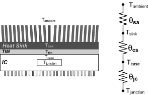
Power is dissipated from the active transistor junctions within an integrated circuit (IC) in the form of heat, with the temperature of the junction being proportional to the power dissipated. Manufacturers specify the maximum junction temperature, though it is generally around 150°C. Exceeding this junction temperature generally results in damage to the device, so designers must look for ways to pull as much heat as possible away from the IC. To do so, they can rely upon a rather simple model to gauge the flow of heat—similar to Ohm’s law for electrical calculations—based on the concept of thermal resistance, symbolized by θ (Figure 1).
 Figure 1: The thermal circuit model for an IC with a heat sink based on the concept of thermal resistance symbolized by θ. (Image source: DigiKey)
Thermal resistance is the resistance that heat meets when flowing from one medium to another. It is measured in units of degrees centigrade per watt (°C/watt) and is defined as:
![]() Equation 1
Equation 1
Where:
θ is the thermal resistance across a thermal barrier in °C/watt.
∆T is the temperature difference across the thermal barrier in °C.
P is the power dissipated in the junction in watts.
Looking at the physical arrangement of the IC and heat sink, there are a number of thermal interfaces. The first is between the junction and the case of the IC, which is modeled by the thermal resistance θjc.
The heat sink is attached to the IC using a thermal interface material (TIM)—either thermal paste or thermal tape—in order to enhance the thermal conductivity between the two devices. This layer, which is generally low resistance, is modeled as part of the case-to-heat sink thermal resistance, θcs. The final stage is the heat sink’s interface to the ambient environment, θsa.
Thermal resistances are added in series just like resistors in an electronic circuit. The sum of all the thermal resistances yields the total thermal resistance from the junction to the ambient air.
The junction-to-case thermal resistance is generally specified, either implicitly or explicitly, by the IC supplier. The specification may be in the form of a maximum case temperature, eliminating one of the thermal resistance elements. The designer applying the IC has no control over the junction-to-case thermal resistance characteristic. The designer does, however, get to select the TIM and heat sink characteristics needed to cool the IC sufficiently to keep the junction temperature below the specified maximum. In general, the lower the thermal resistance of the TIM and heat sink, the lower the case temperature of the IC being cooled.
Heat sink selection example
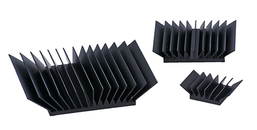
Ohmite offers the BG Series of heat sinks designed to work with ball grid array (BGA) or plastic ball grid array (PGBA) central processing units (CPUs), graphical processing units (GPUs), or similar processors with square package footprints (Figure 2).
 Figure 2: The BG Series of heat sinks are suited to BGA packaged ICs including CPUs, GPUs and others with similarly square footprints. (Image source: Ohmite)
There are ten heat sink designs in the line, with footprints matching common IC configurations from 15 x 15 millimeters (mm) to 45 x 45 mm, and fin areas ranging from 2,060 to 10,893 mm2 (Table 1). These RoHS-compliant heat sinks are made from black anodized 6063-T5 aluminum alloy.
 Table 1: The BG Series range in fin area from 2,060 to 20,893 mm2. (Table source: DigiKey)
The thermal resistance values in the table are for natural convection cooling. Forced convection using a fan, lowers the thermal resistance proportional to the velocity of the cooling air. Forced air cooling can reduce the thermal resistance by a factor of two or three to one (Figure 3).
 Figure 3: The thermal performance of the Ohmite BG Series heat sinks for forced air cooling. (Image source: Ohmite)
Thermal interface materials
In the case of the Ohmite BG Series, the thermal interface material used between the IC case and the heat sink is a double-sided thermal tape, which is supplied with the heat sink. The use of double-sided tape simplifies the installation as the tape does not require any mechanical design or fabrication.
TIMs are usually specified by their thermal conductivity in units of watts per meter-Celsius (watt/(m°C)) or watts per meter-Kelvin (watts/(m°K)). The thermal resistance of the TIM layer is dependent on the thickness of the tape and the area over which it is applied. The thermal resistance can be calculated using the equation:
![]() Equation 2
Equation 2
Where:
The thickness is expressed in meters (m).
The area is expressed in meters squared (m2).
The thermal conductivity is expressed in either watts/(m°C) or watts/(m°K).
Celsius and Kelvin are swappable because they both use the same unit increment of temperature measurement, and it is the difference of temperature that is being calculated (e.g., a 10°C change in temperature is equivalent to a 10°K change in temperature).
Looking at the Ohmite BGAH150-075E 15 x 15 x 7.5 mm heat sink (attached to a 15 x 15 mm device), the area of the TIM is 225 mm2 (225 E-6 m2). The thickness of the thermal tape supplied is 0.009 inches or 0.23 mm (0.00023 m). The specified thermal conductivity is 1.4 watts/(m°K). Using these values in Equation 2 yields:
![]() Equation 3
Equation 3
The thermal resistance of the TIM will generally be much smaller than that of the heat sink, and it will scale lower for heat sinks with a larger footprint area.
An example of the determination of the minimum thermal resistance required in a heat sink to keep the IC within its temperature limit begins with the IC. Consider a 15 x 15 mm IC with a maximum specified case temperature of 85°C, that in normal operation dissipates 2 watts, operating in an enclosure with an ambient temperature of 45°C.
Determining the power dissipation for a processor can be difficult because of the wide range of operating modes. Some manufacturers attempt to simplify this by specifying the thermal design power or TDP. The TDP is the power dissipated when it is running a “real application.” There is some discussion regarding the suitability of this rating since it is dependent on the application. It is also possible to determine the maximum power dissipation by referencing the power supply current requirements for each of the CPU’s supply voltages. This value may be higher than the dissipation described by TDP. Designers should consult the supplier’s technical data to determine the best estimate of an IC’s nominal power dissipation.
Returning to the example, the minimum thermal resistance (θ) of the required heatsink and TIM can be determined using Equation 4:
 Equation 4
The Ohmite BGAH150-075E has a thermal resistance of 18°C/watt; with the added resistance of the TIM, 0.73°C/watt, the total is 18.73°C/watt. This is lower than the calculated minimum thermal resistance and it will work. If this heat sink is selected, based on a reverse calculation using Equation 1 with the ambient temperature held constant, the estimated maximum case temperature would be 82.5°C.
As an alternative heat sink, selecting the 15 x 15 x 12.5 mm Ohmite BGAH150-125E with a greater surface area due to a greater fin height, reduces the total thermal resistance of the heat sink and TIM to 11°C/watt. This would lower the case temperature to about 67°C for about the same cost and provide a greater temperature margin.
Other considerations might be the available space for the heat sink or the possible need of a cooling fan.
Conclusion
Selecting a heat sink is relatively straightforward from a thermal viewpoint. As shown, the Ohmite BG Series heat sinks offer a viable solution to cooling issues on BGA packaged ICs.

Disclaimer: The opinions, beliefs, and viewpoints expressed by the various authors and/or forum participants on this website do not necessarily reflect the opinions, beliefs, and viewpoints of DigiKey or official policies of DigiKey.


