How to Select and Use PC Board Supports to Ensure Cost-Effective and Reliable Electronic Products
Contributed By DigiKey's North American Editors
2023-02-10
Assembly is one of the last remaining steps in the production of most electronic devices, including consumer white goods, general electronics, and automotive applications. It’s usually followed only by a final test and packaging. By the time the device is ready for assembly, most of the cost to produce the device has been incurred. If the assembly process is not robust and cost-effective, it can result in substandard performance, or unnecessarily increase the cost of the device. The use of injection molded printed circuit board (pc board) supports provides electrical isolation and eliminates the need for screws, washers, and nuts while simplifying and speeding final assembly.
Injection-molded pc board supports are deceptively simple-looking components. However, designers need to consider numerous factors when selecting them, including support styles like adhesive base, edge locking, reverse locking, and snap lock, as well as fixing methods including several locking and nonlocking designs, and material choices like acetal, various types of nylon, and ethylene propylene diene monomer (EPDM) rubber.
The selection criteria are further complicated by the need to consider operating temperature, stiffness versus flexibility to handle anticipated vibration levels, and the choice between Underwriters Laboratories (UL) 94V-0 rated parts or less expensive UL 94V-2 rated parts. Additionally, parts used in automotive assemblies need to be rated according to the Society of Automotive Engineers (SAE) J1639 material requirements.
To address these challenges and speed the selection and use of injection molded pc board supports, designers need a supplier that offers a wide range of component types and provides a ‘one-stop shop’ for all pc board support needs.
This article reviews how pc board supports are fabricated using the injection molding process, looks at materials standards and materials choices, and reviews the types of mounting structures and how they are used in pc board supports. It then presents representative pc board supports from Essentra Components and closes with suggestions for the selection process and the integration of the supports into product assembly.
Injection molding
Injection molding of thermoplastics produces highly repeatable and low-cost mechanical components like pc board supports. The process takes place in a series of five stages (Figure 1):
- The thermoplastic pellets are fed into the machine and liquified to a precise temperature.
- The melted thermoplastic enters the injection cavity in preparation for molding.
- When the required pressure is reached in the injection cavity, the melted thermoplastic is injected into the mold using a series of gates to control the flow.
- When the mold has reached the proper capacity, a holding phase starts where pressure is initially maintained on the thermoplastic to ensure the fabrication of consistent parts. In the second part of the holding phase, the pressure is released, and the parts are allowed to cool.
- The mold is opened, and the parts are pushed out of the tool by ejector pins.
 Figure 1: Injection molding can produce low-cost and repeatable pc board supports. (Image source: Essentra Components)
Material standards
Two of the most important material standards for pc board supports are UL 94 flammability requirements and the SAE J1639 classification system for automotive polyamide (PA) plastics. These are general standards that apply to all types of applications, not just pc board supports.
UL 94 has been harmonized with the International Electrotechnical Commission (IEC) standards 60695-11-10 and 60695-11-20, and with the International Standards Organization (ISO) standards 9772 and 9773. These standards classify materials based on their tendency to either spread or extinguish flames once the test part has been ignited.
- V-0 requires that burning stops within 10 seconds (s) on a vertical part and allows drips of material as long as they are not inflamed.
- V-1 requires that burning stops within 30 s on a vertical part and allows drips of material as long as they are not inflamed.
- V-2 is the least restrictive and requires that burning stops within 30 s on a vertical part and allows drips of flaming material.
SAE J1639 is a recommended practice that provides a structure for classification and specification of PA plastics used in automotive applications. It’s based on the American Society for Testing and Materials (ASTM) D 4066 classification system for PA (nylon) injection and extrusion materials. J1639 requires additional descriptive properties and characteristics for automotive PAs. It’s supplemented by proprietary OEM standards from various automakers. The three basic elements of J1639 include:
- Standardization of the grades of reinforced and unreinforced nylons including 66, 6, and 66/6 in automotive applications.
- Standardization of the test methods used to characterize the properties of those PA materials.
- Provide a concise structure for presenting the material specifications.
What material to mold?
Several types of plastics are available. The most common for pc board supports includes acetal, nylons, and EPDM rubber. Depending on the material, they can support operating temperatures from -40˚C to +85˚C, and provide vibration dampening, electrical isolation, and other functions. High temperature materials rated for +200˚C are available for custom designs. Two of the common nylons are PA66 and PA66/6.
For applications that can use a UL 94V-2 material, designers can turn to PA66. Nylon 66 can be especially useful for injection molding processes. It offers a good combination of strength, rigidity, toughness, a high melting point, good surface lubricity (important for injection molding), and abrasion resistance, as well as resistance to many chemicals, machine and motor oils, solvents, and gasoline. In addition, PA66 is relatively inexpensive and is non-halogenated. Parts made with PA66 satisfy the requirements of SAE J1639.
PA66/6 is also non-halogenated and can be used in applications that require a UL 94V-0 rating. Its mechanical properties are similar to PA66 but with improved low-temperature toughness. It can provide a better surface finish and color stability compared with PA66. PA66/6 also meets the requirements of SAE J1639.
Mounting types
In addition to material selection, the specification of mounting type and the fixing method for attaching to the pc board are important considerations for pc board supports. In both cases, there are many options. Some of the most common mounting formats shown in Figure 2 include:
- Threaded, including standard designs that are fastened using washers and nuts, and self-tapping that eliminates the need for washers and nuts.
- Snap fit that pushes quickly into a chassis or panel hole to provide secure mounting. Variations include edge lock, bayonet, fir tree, and others.
- Snap lock also pushes into a chassis or panel hole, but is easily removed.
- Press fit, blind attach, that uses fins to provide a secure hold. They can be especially useful in space-restricted applications.
- Adhesive base that uses tape to eliminate the need for a mounting hole.
 Figure 2: Five of the many choices for connecting pc board supports to panels or chassis. (Image source: Essentra Components)
Pc board fixing methods
The second, and equally important design decision is the selection of a pc board fixing method. As with panel mounting types, there’s a large selection of fixing methods, the examples shown in Figure 3 include:
- Two-prong snap lock with two-prong snap fit, where one side locks and the other side is releasable for stacking pc boards or connecting a pc board to a chassis.
- Arrowhead snap lock with bayonet nose snap fit provides a very secure hold and supports quick assembly in stacking applications.
- Flat rest mount is a self-adhesive pc board support with a quick release tab.
- Hexagonal/threaded mounts securely with a hex nut and has a releasable, low-profile fastener on the other side.
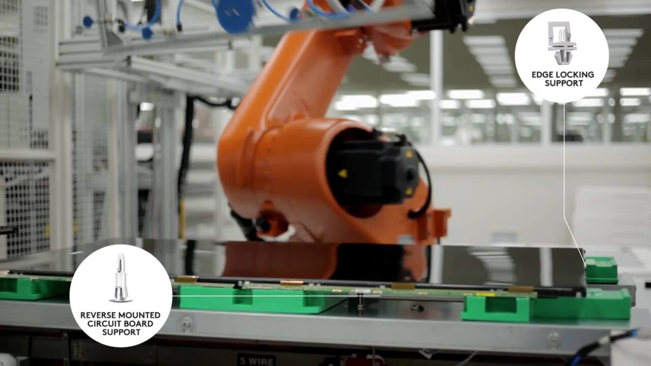
- Reverse dual-locking/snap fit provides a snap fit for secure connection to the pc board. It can be installed from the underside of the chassis and has a thin button head to minimize protrusion.
 Figure 3: Several options for fixing supports to pc boards. (Image source: Essentra Components)
Pc board support examples
Given the vast range of combinations of materials, mounting types, and fixing methods, it’s not possible to present a complete picture of pc board support options. The following are a few of the hundreds of options available from Essentra Components:
The CRLCBSRE-10-01, fabricated with nylon 66, meets UL 94V-2 and is similar to part “E” in Figure 3 above. The upper part fits a 4 millimeter (mm) hole and the bottom fits a 5.4 mm hole. The overall spacer length is 15.9 mm (0.625 inches (in.)).
The PSM-10-01 is also made with nylon 66. It has a flat rest on one side and a locking arrowhead (like the top of part “B” in Figure 3) that fits into a 0.125 in. hole on the opposite side. The arrowhead length is 0.130 in. and the spacer length is 15.9 mm (0.625 in.). It’s designed to fit panels up to 0.078 in. thick.
The RLEHCBS-7-01BK is a reverse mount, edge-holding support that is made with black nylon 66 and mounts into a 0.375 x 0.313 in. bottom hole in a 0.062 in. thick panel (Figure 4). The top board has a 0.156 in. hole and locks onto a 0.062 in. panel. The spacer length is 0.500 in.
 Figure 4: The RLEHCBS-7-01BK has an edge-holding support for fixing to the pc board. (Image source: Essentra Components)
Choice of UL 94V-0 or V-2 and another design option
The following supports are available in either PA66/6 or PA66.
For installations that need a flat mount with a mounting hole on one side and a locking arrowhead on the opposite side, designers can choose from the UL 94V-2 rated CBSS-10-01 (Figure 5) or the UL 94V-0 rated CBSS-10-19.
 Figure 5: The CBSS-10-01 is an example of a support with a locking arrowhead on one side and a flat mount with a hole on the other. (Image source: Essentra Components)
For applications that need a spacer similar to “A” in Figure 3, designers can turn to the UL 94V-2 rated MSPM-5-01, or the UL 94V-0 rated MSPM-5-19.
And for applications where a design similar to “B” in Figure 3 is needed, designers can consider the UL 94V-0 rated LCBS-2-12-19, or the UL 94V-2 rated LCBS-2-12-01.
Conclusion
As shown, pc board supports are available in a wide range of shapes and sizes and are made with several material types. Add to that the need to support efficient and reliable assembly, among other application requirements, and the selection process can be daunting. In most cases, the best advice for designers is to select one or more options that appear suited to the application, and then experiment to determine which one best supports the overall assembly requirements.
Recommended reading
Disclaimer: The opinions, beliefs, and viewpoints expressed by the various authors and/or forum participants on this website do not necessarily reflect the opinions, beliefs, and viewpoints of DigiKey or official policies of DigiKey.