How to Select and Apply Electromechanical Relays for Versatile and Reliable Signal Switching
Contributed By DigiKey's North American Editors
2024-08-20
Applications such as telecom and network devices, automatic test equipment (ATE), and security devices increasingly need to reliably switch and route single or multiple low-to-moderate-level DC, AC (analog), and radio-frequency (RF) signals. Electromechanical relays (EMRs) are well-suited to handle this task.
EMRs offer outstanding on and off performance along with input/output isolation and are available in multiple pole configurations to provide designers with flexibility and versatility. Further, a single relay can support different signal types (AC, DC, low frequency, RF) in the same device, adding to their value.
Although they have moving parts and physical contacts, they are fully characterized due to their long application history. As such, they are reliable “problem solvers” that can provide many years of consistent service. While EMRs are also inherently rugged devices, designers must select an appropriate relay (both coil and contact ratings) and use it properly to ensure maximum longevity.
This article briefly discusses signal relay types and applications. It then describes how to select and apply EMRs using examples from Omron Electronic Components.
Relay types and differentiation
EMR refers to a component with many application-specific subtypes. For example, power relays have contacts rated at 2 A or higher, while signal relays are designed for contact currents below that value.
Signal relays can be divided into two groups: non-RF signals and RF signals. While all relays are characterized by basic continuity parameters and current and voltage-handing maximums, there are additional performance metrics for RF relays. These include:
- Isolation: High-frequency signals leak through the stray capacitance across contacts, even if the contacts are separate. Isolation is measured in decibels (dB).
- Insertion loss: At high frequencies, signal disturbances arise due to self-induction, resistance, and dielectric loss, as well as from reflections due to impedance mismatches. Insertion loss is also measured in dB.
- Voltage standing wave ratio (VSWR): This is due to constructive/destructive interference between an input signal wave and any reflected signal. This measurement is a unitless number indicating the ratio of a maximum waveform value to its minimum value.
Simplifying the bill of materials
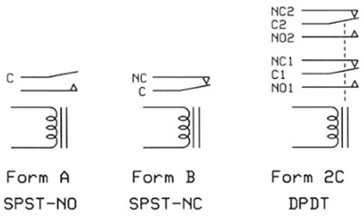
Relay configurations are defined by their number of contacts or poles (P) and normal (meaning unpowered) open/close contact situations (Figure 1). They can be normally open (NO) or normally closed (NC). Single pole (SP) and double pole (DP) configurations are most common, although units with more contact poles are available. The throw (T) is the extreme position of the actuator.
 Figure 1: Shown are contact arrangements and industry-standard designations for several types of EMRs; the dashed lines in the Form 2C relay indicate both armatures have a non-conductive link that moves both contacts simultaneously when the relay coil receives current. (Image source: Sealevel Systems, Inc.)
The ability of EMRs to support multiple poles and NO/NC throws highlights how they can simplify circuitry, save board space, trim the bill of materials (BOM), and lower cost. The reason is that a single relay can switch multiple circuit paths to all-on, all-off, or a combination of each, depending on the pole and throw configuration. That same relay can also switch both AC and DC signals, providing simultaneous operation across multiple circuit paths.
In some cases, EMRs with an extra pole pair are used to power an auxiliary circuit, such as an LED circuit to indicate to users that the relay has been energized and has created the desired contact state. Further, some experienced designers use a double pole, double throw (DPDT) relay when all they need is a single pole, double throw (SPDT) unit (SPDT and DPDT relays have the same footprint in many cases), giving them a “just in case” contact pair to fix a problem or oversight that is discovered later in the design cycle.
The G6J-2P-Y DC12 (Figure 2) from Omron is an ultra-slim DPDT (Form 2C) relay with a 977 ohm (Ω) coil and is designed to be driven by 12 V at 12.3 mA. Note that other members of this family offer different coil voltage/current pairings up to 24 VDC for compatibility with almost any drive circuit or situation.
 Figure 2: The G6J-2P-Y DC12 is an ultra-slim DPDT relay with a 12 V, 12.3 mA coil; it is part of a family of relays with identical size and contact ratings but different coil voltage/current combinations. (Image source: Omron)
This diminutive relay is suitable for high-density printed circuit (pc) boards, as it measures just 5.7 × 10.6 × 9 millimeters (mm). The G6J-2P-Y DC12 comes with through-hole terminals, but identical versions offer short and long surface-mount terminals for maximum flexibility. The contacts of this relay and all others in this family are rated to handle up to 0.3 A at 125 VAC and 1 A at 30 VDC.
Relays and RF
Relay uses are not limited to providing simple “dry” contact closures or handling DC voltages/currents and lower-frequency AC signals. Some models are designed explicitly for ultra-high-frequency applications, such as ATE.
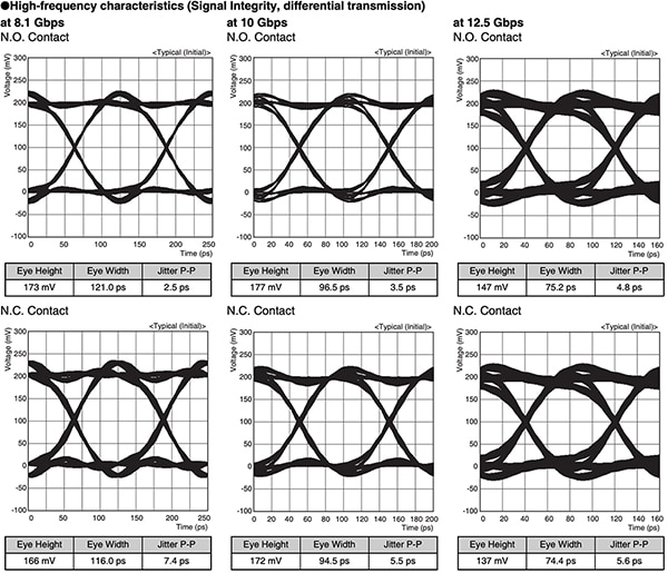
The Omron G6K-2F-RF-V DC4.5 is a miniature surface-mount DPDT relay supporting differential-transmission signal switching. Insertion loss for this 11.7 × 7.9 × 7.1 mm relay is 3 dB or less at 8 gigahertz (GHz). It can also be used at higher frequencies, as its eye diagram shows for a 200 mV differential signal with a 25 picosecond (ps) rise time (Figure 3).
 Figure 3: The G6K-2F-RF-V DC miniature surface-mount DPDT relay uses differential-transmission signal switching and is specified to 8 GHz and beyond, as seen by these eye diagrams with 8.1, 10, and 12.5 gigabit per second (Gbit/s) signals. (Image source: Omron)
This GHz-range performance is due, in part, to an electrical and mechanical design that inherently supports differential signals. This helps ensure desirable performance as defined by RF isolation (unrelated to galvanic isolation), insertion loss, and VSWR (Figure 4).
 Figure 4: The G6K-2F-RF-V gigahertz relay uses an inherently differential design that eases circuit board physical layout issues and minimizes the detrimental impact of that layout on RF performance. (Image source: Omron)
The relay uses an advanced internal layout that simplifies the PC board layout and eliminates the need for complex multilayer signal-path routing on the board, which degrades RF performance. Its use of a resin case rather than a metal one avoids the problem of probe pins short-circuiting through a metal case and causing damage to the board and parts while inspecting the relay mounting.
Relays and power consumption
Power consumption is a critical parameter in nearly all circuits and systems. It defines supply sizing, affects run time for battery-operated designs, and the associated heat impacts thermal performance. This has implications for conventional non-latching relays, where the coil must remain powered for the entire time the relay needs to be energized.
Alternative architectures to the basic on/off design (formally called single-side stable) address this concern. The latching relay (also called a keep relay) is designed so that once it is energized, it remains in that position even after coil power is removed.
There are several ways to implement the latching function. The G6JU-2P-Y DC3, and others in this family, use a single-winding latching technique in which the “set” input pulse causes the operating condition to be maintained via an adjacent permanent magnet. The “reset” input pulse (an input with the inverse polarity of the set input) puts the relay into an unlatched state.
Relays and reliability
Relays have moving parts and physical electrical contacts, so it is normal to assume that they will become unreliable after a modest number of on/off cycles. However, that is not the case.
First, the different effects of opening and closing contacts when carrying AC versus DC at various levels are well understood and are called out in detail on the relay’s datasheet. Premature contact wear should not be an issue if the defined conditions are respected.
Equally important is that decades of use, experience with countless units in the field, metallurgical research and development, modeling and analysis, controlled life tests, production and fabrication improvements, and other technical factors have transformed coil and contact design and fabrication into well-understood, mature, and sophisticated processes, and resultant components.
Relay durability is connected to contact and coil durability. Coil durability starts with a standard value of 40,000 hours, as there is a decrease in insulation properties due to heat generated when the rated voltage is continuously applied to the coil. If the relay use is intermittent, the coil durability is much longer.
Durability is also assessed by two factors often called out on datasheets:
- Mechanical durability is the number of times a relay can open and close the contact with no load, taking into account mechanical malfunctions and characteristics.
- Electrical durability is the number of times a relay can open and close the contact with a rated load (such as 125 VAC, 0.3 A / 30 VDC, 1 A).
Relay contacts come in different configurations with increasing levels of long-term reliability: single contact, twin contact, and cross-bar twin contact (Figure 5). The design of the cross-bar twin contact provides exceptionally stable contact resistance and minimizes contact failure. The G6J-2P-Y family members have a bifurcated crossbar (similar to the cross-bar twin contact) with a silver contact plated with a gold alloy.
 Figure 5: Relay contacts have improved and evolved from basic single contact to longer-life, cross-bar twin contacts that offer consistent performance and stable contact resistance. (Image source: Omron)
The known reliability of these relays makes them a good choice for any application where downtime or service interruptions are not acceptable, or relay performance is a mission-critical consideration.
Conclusion
EMRs are critical problem-solving components in many of today’s systems, addressing and resolving many signal-path issues. They offer unique and irreplaceable signal-handling attributes, well-defined performance, and long-term reliability. Signal relays are available for DC, low-frequency, and even RF applications into the GHz range, thus broadening their applicability.

Disclaimer: The opinions, beliefs, and viewpoints expressed by the various authors and/or forum participants on this website do not necessarily reflect the opinions, beliefs, and viewpoints of DigiKey or official policies of DigiKey.


