How to Quickly Implement Reliable Touchscreens
Contributed By DigiKey's North American Editors
2024-01-17
A touchscreen is increasingly preferred over a keyboard and mouse as a human-machine interface (HMI) for programming, configuring, and controlling consumer, enterprise, and industrial systems. Touchscreens are intuitive, fast, and have a single integrated interface that replaces a combination of input devices. They also offer greater convenience for people with physical challenges and can be made quite compact.
The wide variety of applications for touchscreens means they must be rugged, operable by a bare or gloved finger, and cost-effective. Resistive touchscreens meet these requirements, but designers need to be able to get to market quickly with off-the-shelf solutions comprising a touchscreen matched to an appropriate controller. They must also understand the differences between 4 and 5-wire resistive touchscreen interfaces.
This article briefly describes resistive touchscreens. It then introduces example touchscreens and controllers from NKK Switches and shows how to design with them.
How resistive touchscreens work
Resistive touchscreens are standalone components that overlay a flat panel display. In conjunction with a controller, a touchscreen lets users interact with displayed symbols by touching specific areas. A touchscreen can detect the precise position of a finger or stylus touch. Application software then determines what further screen actions should occur based on that position.
Resistive touchscreens are suited to various consumer, retail, enterprise, industrial, and medical applications because they are inexpensive, rugged, and can be operated with a bare finger, a gloved hand, or a stylus. The technology uses a deformable plastic film that is coated on its back side with a conductive layer such as indium tin oxide (ITO). The back of the touchscreen is formed from a glass or acrylic panel, which includes an ITO layer on its front face.
Non-conductive spacer dots separate the plastic film from the glass or acrylic backing panel. When the plastic film is pressed with a finger or stylus with a force of one or two newtons (N), the film contacts the backing panel, effectively closing a switch in the local pressure area. The controller board, with an attached four or five-wire connector, can determine the location of the closed switch, and the software responds accordingly (Figure 1).
 Figure 1: Resistive touchscreens work by using a touch to press together two conductive surfaces. (Image source: NKK Switches)
Resistive touchscreens are popular when cost, ruggedness, and operation with a gloved hand or non-conductive stylus are essential. They are typically capable of millions or even tens of millions of operations without failure. Resistive touchscreens can also be manufactured with protection against water and chemical splashes.
The difference between 4 and 5-wire touchscreen configurations
A 4-wire touchscreen employs two electrodes on the bottom plate and two on the top plate. On the bottom plate, the electrodes run along the Y axis, enabling resistance to be measured along the X axis. Similarly, the top plate has edge electrodes that run along the X axis, enabling the resistance to be measured along the Y axis (Figure 2).
 Figure 2: 4-wire resistive touchscreens use two edge electrodes on the bottom plate and two on the top plate. The pairs run perpendicular to each other and allow the XY position of a touch to be determined. (Image source: NKK Switches)
At the point of finger contact, the bottom layer effectively divides the top layer into two resistors in series. The bottom layer is similarly divided at the point of contact with the top layer. With appropriate biasing, each plate can function as a divider where the output voltage represents the point of contact coordinates.
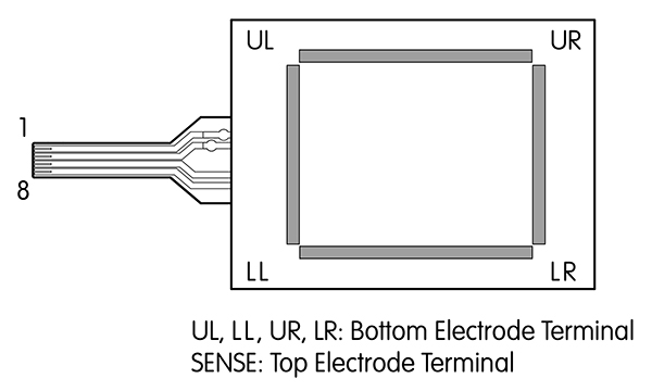
In a 5-wire system, the top plate has four edge electrodes and functions as the voltage sensing node. The four corners of the bottom plate form electrodes that produce voltage gradients in the X and Y directions. Different bias configurations are used to obtain the X and Y direction measurements (Figure 3).
 Figure 3: 5-wire resistive touchscreens use four corner electrodes on the bottom plate to produce voltage gradients in the X and Y directions and two pairs of edge electrodes on the top plate to sense voltage. (Image source: NKK Switches)
In the 5-wire construction, only the bottom plate is active. That means the top plate can sustain damage, yet the touchscreen can still operate. In contrast, both plates of the 4-wire touchscreen are active; damage to the top plate can cause the touchscreen to fail. The 5-wire touchscreen tends to be more durable, but the trade-off is increased design complexity and expense.
Commercial resistive touchscreen solutions
To minimize complexity and accelerate time to market, NKK has proven commercial solutions for both the touchscreen and the matching controller. The designer still has the option to source a touchscreen from NKK and match it up with a controller from a different supplier, or one of their own.
The FT series from NKK is an excellent example of resistive touchscreens. Available in a variety of screen sizes ranging from 5.7 to 15.6 inches (in.) (diagonal), the series is offered in both 4 and 5-wire configurations with a touch activation force of 1.4 N (Table 1). Both versions feature a flexible circuit tail that connects to a controller board.
|
Table 1: A comparison of 4 and 5-wire resistive touchscreens shows the 5-wire version offers longer operational life, measured in tapping operations. (Image source: NKK Switches)
The FTAS00-5.7AS-4A is a 4-wire, 5.7 in. model that draws 1 milliampere (mA) at 5 volts DC (VDC), has an XY resistive value of 250 to 850 ohms (Ω), a linearity of 1.5%, and an insulation impedance of 10 megaohms (MΩ). The touchscreen’s expected operational lifetime is 50,000 writing or one million tapping operations.
The FTAS00-10.4A-5 is a 5-wire, 10.4 in. model that draws 1 mA at 5.5 VDC, has an XY resistive value of 20 to 80 Ω, a linearity of 2%, and a minimum insulation impedance of 10 MΩ. The operational lifetime is 50,000 writing or 10 million tapping operations.
For both the 4 and 5-wire touchscreen products, NKK offers a controller with either an RS232C or a USB interface. The controller boards are supplied with device driver software compatible with Windows 7, 8, and 10. The FTCS04C and the FTCU04B are the RS232C and USB interface controller boards for the NKK 4-wire touchscreens, respectively, while the FTCS05B and the FTCU05B are the equivalents for the 5-wire touchscreens.
Getting started with a resistive touchscreen
The design process is similar for the 4 and 5-wire touchscreens. At the heart of the RS232C and the USB 4-wire controller board is the FTCSU548 controller chip. This 48-pin LFQFP IC has an asynchronous serial interface and a full-speed USB 2.0 interface. It is powered by a 3.3 to 5 volt supply for RS232C operation or a 5 volt supply for USB, with a rated output current of 170 mA, an operating frequency of 16 megahertz (MHz), and an analog-to-digital converter (ADC) resolution of 10 bits. The chip features a built-in calibration function.
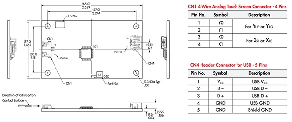
When the touchscreen is pressed, the controller IC determines the coordinates using the value of the analog voltage detected by the ADC and forwards them to the host computer via the RS232C or USB interface (Figure 4).
 Figure 4: The FTCSU548 controller IC (IC1) is mounted on the FTCU04B (4-wire USB) controller board. CN1 (left) is the connector for the touchscreen’s 4-wire flexible circuit tail. (Image source: NKK Switches)
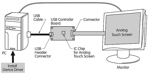
The touchscreen’s 4-wire flexible circuit tail is connected to the controller board via CN1. The controller board connects to the host PC via CN4. The CN4 USB interface also supplies power to the board. The host runs the device driver and touchscreen application software (Figure 5).
 Figure 5: Shown is a typical 4-wire USB controller board and host PC configuration. (Image source: NKK Switches)
Design tips
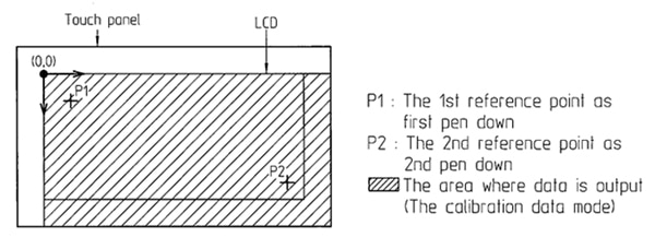
The resistive touchscreen requires calibration upon installation. The FTCSU548 controller IC includes a built-in calibration function. The controller IC must first be set to “source data mode” to calibrate. The PC then indicates a reference point (P1) on the touchscreen that the operator presses with a stylus, and the ADC voltage information is sent to the PC via the controller board. The process is repeated with a second point (P2) in a distant touchscreen area. The physical coordinates of P1 and P2 are sent to the PC as an eight-byte number. The touchscreen is then set into “calibration data mode,” and the application software uses the voltage and coordinates reading for the two known points, plus a built-in “0,0” reference, to interpolate all other coordinates in the calibration data mode area (Figure 6).
 Figure 6: Calibration is required during initial configuration and periodically afterward because the resistance changes as the touchscreen ages. (Image source: NKK Switches)
The screen's resistance changes as it ages, so recalibration is required throughout its operational life.
It is essential to include grounding for the display device frame to prevent electromagnetic interference (EMI). It is also possible that the initial contact resistance from a finger might cause ‘chatter.’ To prevent chatter, a built-in delay can be used to allow the voltage to settle before the system calculates the coordinates.
Designers must also be careful not to include software instructing users to touch two touchscreen areas simultaneously. The technology cannot resolve two separate touches and defaults to a center point between them. Finally, breaks will appear above the screen spacer when a line is drawn on a screen using a stylus, separating the two layers. Designers should ensure the application software fills in those gaps.
Conclusion
Resistive touchscreens are suitable HMIs in applications where cost, ruggedness, and operation with a bare or gloved hand or non-conductive stylus are essential. To simplify implementation, commercial solutions from NKK include the touchscreen overlay, controller boards with a dedicated controller IC, and device driver software.

Disclaimer: The opinions, beliefs, and viewpoints expressed by the various authors and/or forum participants on this website do not necessarily reflect the opinions, beliefs, and viewpoints of DigiKey or official policies of DigiKey.


