How to Protect Power Line Communication (PLC) Systems: Two Technologies to Know
Contributed By DigiKey's North American Editors
2023-08-09
Designers of smart energy infrastructure, such as smart grids, smart meters, and intelligent street lighting, need reliable, cost-effective, and secure communications. While wireless technologies have a role to play, their vulnerabilities, costs, and coverage limitations present significant challenges. Power line communication (PLC) technology, which enables data transfer over existing power lines, presents a good foundational technology to base critical communications.
Though PLC is well-defined and widely used, there are some issues designers need to be aware of that can disrupt communication, such as signal attenuation, noise, and voltage transients. Addressing these issues requires practical and efficient solutions to ensure optimal performance. Two such solutions are PLC transformers and GMOV overvoltage protectors.
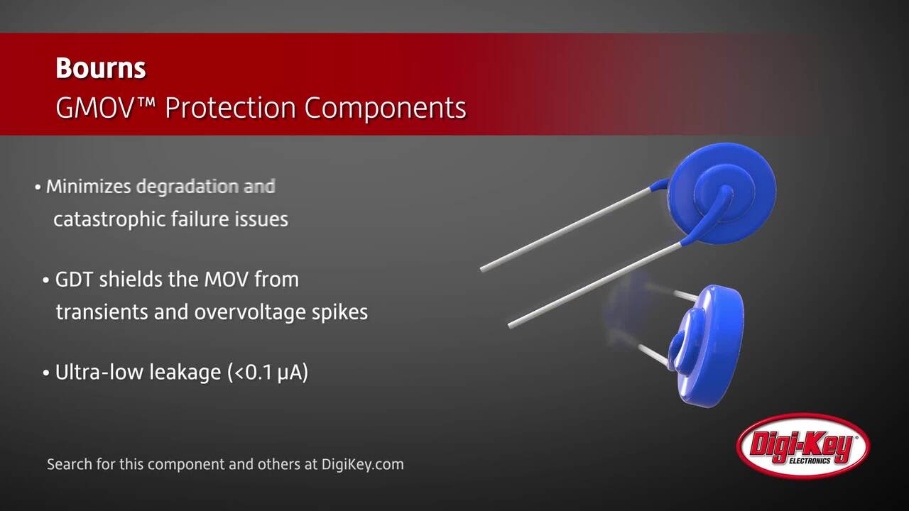
PLC transformers are optimized for minimal insertion loss within narrowband (NB) applications. They also reduce galvanic isolation and electromagnetic interference (EMI), enhancing signal quality and reliability. A GMOV is a hybrid overvoltage protection component that combines a gas discharge tube (GDT) and a metal oxide varistor (MOV). It is designed to overcome the limitations and failure issues of standard MOVs, which are susceptible to degradation and thermal runaway in harsh and uncontrolled environments.
This article briefly reviews how a PLC operates and why it is suited to smart infrastructure. It then introduces PLC transformer and GMOV protector examples from Bourns, shows how they work, and presents some factors to consider when choosing and applying them.
PLC operation, applications, and challenges
In a PLC system, the data to be transmitted is modulated onto a carrier signal and injected into the power line. The details vary widely between applications, but IEEE 1901.2 is the global standard for power grids. It specifies low-frequency (≤ 500 kilohertz (kHz)) NB communications up to 500 kilobits per second (Kbits/s), and is suitable for applications like smart grids, smart meters, and intelligent street lighting.
While PLC technology has proven to be a useful solution for designers of smart energy infrastructure, it is not without its challenges. Design hurdles include signal attenuation, noise, and voltage transients, all of which can significantly degrade communication quality and reliability. Specifically:
- Signal attenuation is an issue because PLC signals use lines that were designed for power, not data. These lines have impedance characteristics that can impose considerable attenuation, particularly over long distances. The resulting drop in signal strength can reduce effective range and potentially lead to data loss or error.
- Noise can be introduced from various sources, such as electronic appliances connected to the power lines, power supply variations, and external EMI. The relatively high-frequency nature of PLC data signals makes them particularly susceptible to these sources of noise within the unshielded power grid.
- Voltage transients can occur due to lightning strikes or switching of inductive loads. Such transients can induce high voltages on the power line, potentially damaging the PLC modems.
When addressing the challenges faced by PLC systems, designers have two key technologies they can apply: PLC transformers and GMOV protectors. Both components serve crucial roles in ensuring the reliability, performance, and safety of PLC systems.
Design review: PLC transformers and GMOVs in the coupling circuit
To illustrate the issues PLC transformers and GMOVs can address, consider the coupling circuit illustrated in Figure 1. This circuit must isolate the PLC modem (ZModule) from the mains line (ZLine) while also providing a path for the data signal. While doing so, the coupling circuit must handle both high-frequency, low-power communications and low-frequency, high-power AC.
 Figure 1: Shown is a simplified coupling circuit with surge protection that isolates the PLC modem (ZModule) from the mains line (ZLine), while also providing a path for the data signal. (Image source: Bourns)
The PLC transformer (T1) provides galvanic isolation between the PLC modem and the power line, helping separate the PLC from the AC mains. A key characteristic of these transformers is their minimal insertion loss, which reduces signal distortion and attenuation. For example, Figure 2 shows the performance of Bourns’ PFB Series of PLC transformers, which are optimized for NB applications below 500 kHz. Moreover, a PLC transformer's ability to suppress EMI helps reduce noise, contributing to more reliable and efficient communication.
") Figure 2: Shown is a graph of insertion loss versus frequency for the PFB Series PLC transformers that are tailored for NB applications below 500 kHz. (Image source: Bourns)
Figure 2: Shown is a graph of insertion loss versus frequency for the PFB Series PLC transformers that are tailored for NB applications below 500 kHz. (Image source: Bourns)
In Figure 1, again, voltage transients are handled by the GMOV protector (Figure 3). This novel device is a hybrid overvoltage protection component that integrates the rapid response of an MOV and the high surge-current-handling capability of a GDT. This combination provides robust protection against voltage transients caused by lightning strikes or switching events that can damage electronic circuits in PLC systems.
In a GMOV, the MOV and GDT components are capacitively coupled in a series configuration. Under low-frequency conditions, the voltage limiting of the GMOV component equals the sum of the voltage limiting of the MOV and GDT components.
 Figure 3: The GMOV combines the rapid response of an MOV with the high surge-current-handling capability of a GDT. (Image source: Bourns)
Unlike standard MOVs, which are prone to degradation and thermal runaway, the GMOV protector is designed to withstand harsh and uncontrolled environments. The MOV component clamps excessive voltages to safe levels, while the GDT acts as a fail-safe during extreme surge conditions. This function redirects excessive energy away from the MOV, thus extending its life and reducing the likelihood of system failure.
Design considerations for PLC transformers and GMOV protectors
Designing a line coupling circuit for a PLC system requires careful consideration of key components and their interactions. Here are some of the issues to factor into the design.
PLC system requirements: Before starting the design process, have a clear understanding of the PLC system’s requirements. This includes the required data rate, the range of operation, the type of power lines it will operate on, and the environmental conditions to which it will be exposed.
Safety and compliance: Safety is of particular concern for designs to which users or maintenance workers may have access. Depending on the application, the design may require compliance with EN 62368-1 (IT and audio-visual equipment) or EN 61885 (communication networks and power utility automation).
From a communications perspective, designs typically must comply with the European CENELEC EN 50065-1 standard, which defines maximum signal levels as well as permissible carrier frequency bands.
Selecting a PLC transformer: Check that the transformer meets operating frequency, voltage, and impedance requirements. For example, the Bourns PFB Series mentioned earlier are optimized for NB PLC (NB-PLC) applications, making them suitable for long-distance operation. With support for low and medium voltage ranges, the PFB Series can be used for both indoor and outdoor settings.
Be sure to choose a transformer with a turns ratio that enables the PLC modem impedance to match the power line impedance. Many times, the modem impedance cannot be changed, so the transformer must be carefully selected to achieve an impedance match for efficient signal transmission.
Also, consider the application environment. For instance, the PFB Series is available in both a standard and elongated form. The standard model PFBR45-ST13150S is designed for use within secured housings, while the elongated model PFB45-SP13150S adds safety features for use in areas where maintenance workers or users may have access to it. The reinforced insulation of this latter model protects against electric shock and isolates the end user from hazardous input voltages. Figure 4 illustrates the key characteristics of the two models.
| |||||||||||||||||||||||||||||||||||||||||||||||||||
Figure 4. The elongated PFB45-SP13150S PLC transformer has more robust safety features compared to the PFBR45-ST13150S. (Image source: Bourns)
Selecting a GMOV protector: Consider what kinds of power surges and voltage transients the system might face when selecting a suitable protector. For example, Bourns offers 14 millimeter (mm) GMOV protectors like the GMOV-14D301K that support surge currents of 6 kiloamperes (kA), as well as 20 mm variants like the GMOV-20D151K that support surge currents of 10 kA. Notably, both the 14 and 20 mm variants are compatible with standard MOVs in size and footprint. Figure 5 provides the full list of configurations available for these devices.
| ||||||||||||||||||||||||||||||||||||||||||||||||||||||||||||||||||||||||||||||||||||||||||||||||||||||||||||||||||||||||||||||||||||||||||||||||||||||||||||||||||||||||||||||||||||||||||||||||||||||||||||||||||||||||||||||||||||||||||||||||||||||||||||||||||||||||||||||||||||||||||||||||||||||||||||||||||||||||||||||||||||||||||||||||||||||||||||||||||||||||||||||||||||||||||||||||||||||||
Figure 5: GMOV protectors come in 14 and 20 mm variants, with the latter supporting higher surge currents. (Image source: Bourns)
It’s also important to keep capacitance and leakage current in mind. High capacitance can impede data transmission in PLC systems. Bourns GMOV protector's low capacitance of less than 2 picofarads (pF) minimizes signal distortion, which means it does not significantly affect data transmission over the power lines.
Bourns GMOV protectors also feature less than 1 microampere (µA) of leakage current. Although leakage may seem like a trivial matter, it adds up in city-scale applications. For example, in a street light application with a leakage current of 10 microamps, multiplying this by the one million street lights in a typical urban area, the energy loss due to leakage becomes significant.
Conclusion
The advent of smart energy infrastructure—characterized by smart grids, smart meters, and intelligent street lighting—has brought the need for reliable, cost-effective, and efficient communication systems to the forefront. As shown, PLC is a suitable option, particularly when supported by specialized PLC transformers and GMOV protectors to ensure signal quality and reliability, and to protect against transients or surges, while minimizing leakage current.
Disclaimer: The opinions, beliefs, and viewpoints expressed by the various authors and/or forum participants on this website do not necessarily reflect the opinions, beliefs, and viewpoints of DigiKey or official policies of DigiKey.