How to Overcome Design Challenges for Fast and Efficient EV Charging Infrastructure
Contributed By DigiKey's North American Editors
2023-10-04
Electric vehicle (EV) charging solutions need a range of power conversion technologies to support alternating current (AC) designs for home and office chargers, and direct current (DC) fast charging systems for charging on extended road trips. The common thread between all types of EV chargers is the need for a variety of contactors, relays, connectors, and passive components necessary to support the high voltages and currents present, as well as deliver the compact designs and high efficiencies needed to support a faster, safer, smaller, efficient, and flexible EV charging infrastructure.
Designing efficient and flexible EV chargers requires a variety of compact, high-voltage devices. These devices must deliver low electrical resistances with reliable and safe operation. In some cases, these devices also need long electrical switching lives when exposed to harsh operating environments. Some safety devices, like emergency shut-off switches, are required to be IP67 qualified. Others, like electromagnetic interference (EMI) filters, terminal blocks, and contactors, must have specific international performance certifications.
This article provides an overview of AC and DC EV charger designs and some related regional standards. It reviews the need for higher-power EV chargers and looks into the future of extreme fast charging (XFC). It closes by briefly presenting uses for contactors, relays, connectors, power resistors, switches, EMI filters, and power block interconnect systems in EV charging systems and includes links to exemplary products from TE Connectivity.
Regional standards
There are a variety of standards that define AC and DC EV charging. Each region has its own approach. In North America (NA), SAE J1772 describes three levels of EV charging, whereas IEC 61851 is used in Europe and details four charging modes. The standard in China is GB/T 20234 for both AC and DC charging, while in Japan, there’s the Japan Automobile Research Institute (JARI) standard for AC charging and CHAdeMO for DC charging. AC charging is typically used up to around 22 kW, while DC charging delivers more power. In addition, AC charging requires an onboard charger (OBC), while DC chargers connect directly to the battery pack (Figure 1). A brief comparison of charging standards in NA and Europe will provide context for the next section on charger designs and use cases.
 Figure 1: AC charging uses an OBC, while DC charging feeds energy directly into the battery. (Image source: TE Connectivity)
NA has two levels of AC charging. Level 1 uses a wall outlet to deliver up to 1.9 kW, while Level 2 uses a charging station for up to 19.2 kW. Level 1 chargers are primarily utilized in residences, while Level 2 are found in residential and commercial settings. Europe has three modes of AC charging. Mode 1 is like Level 1 in NA, while Mode 3 is like NA Level 2. Europe also has an intermediate type, Mode 2, that uses a wall plug like Mode 1 but adds protective circuitry to the connecting cable enabling it to deliver twice the power.
Fast is not enough
Fast AC chargers, like Level 2 in NA and Mode 3 in Europe, are faster than the alternatives that take up to 10 to 12 hours to fully charge an EV. That said, fast AC can still take several hours to recharge a depleted battery pack, which is useful in cases where a car will be parked at an office, home, or another location for an extended period. However, it is still not fast enough to significantly reduce range anxiety among EV drivers.
That’s why high-power Mode 3 AC chargers and Level 4 DC chargers were developed. The charge rate for DC fast charging depends on how much current is available from the charger and the voltage of the battery pack. DC fast chargers were initially developed for 400 V battery packs. To achieve 80% charge with a 400 V, 200 A charger takes about 50 minutes. Upping the current to 350 A is challenging, but doing so can deliver an 80% charge to a 400 V pack in about 29 minutes. Although raising the current decreases the necessary charging time, more is needed to make EV charging a time-efficient alternative to other fueling methods. The goal is a charge time of 10 minutes – about the same amount of time necessary to fill the gas tank of an internal combustion engine (ICE) vehicle.
The next phase of DC fast charging will be extreme fast charging (XFC). To get to XFC, battery pack voltages are rising from 400 V to 800 V, with 1 kV packs on the horizon. XFC charger technology is being developed to deliver 1 kV at 350 to 500 A, bringing charging times down to 10 minutes or less. With advances in XFC, range anxiety will become obsolete.
In addition to developing XFC technology, designers are pressed for compact designs and high efficiencies to support safer, smaller, more efficient, and flexible EV charging. That requires advanced components and advanced designs.
 Figure 2: Advanced components are needed to develop more compact and higher-power charging solutions for electric vehicles. (Image source: TE Connectivity)
Getting into tight spaces
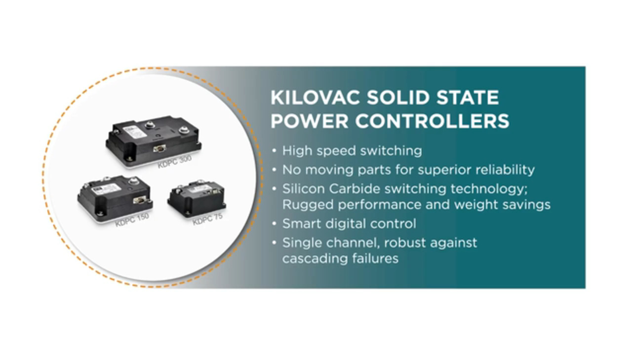
XFC charger designs are being developed using silicon carbide (SiC) and gallium nitride (GaN) power semiconductors that deliver highly-efficient, compact power conversion solutions. However, power conversion is only one element of EV charger design.
EV chargers need compact and robust board and signal connectors for control and monitoring. They need space-efficient relays and contactors that can handle the higher voltages associated with faster-charging regimes. Power resistors in EV chargers need high insulation resistance, low surface temperature, excellent temperature coefficient of resistance (TCR) performance, the capability to dissipate high power in a limited space, and fireproof construction.
Auxiliary power supplies and other circuitry depend on compact electromagnetic interference (EMI) filters to eliminate interference with control logic and monitoring circuits. Emergency shut-off switches with IP65 rating and enough actuation force to prevent unintended switching are necessary to withstand harsh environments.
Level 2 / Mode 3 AC Chargers
The following list details some key components required when designing Level 2 and Mode 3 AC chargers. The listed numbers correspond to the circled numbers in Figure 3 below.
- Power relays, like TE’s T92 series, are used as the main switch in AC charging stations. These two-pole single-throw (DPST) relays are rated for up to 50 A and designed for use in extreme temperatures. Model T92HP7D1X-12 is optimized for superior thermal performance and rated for 50 A and 600 Vac at up to 85 °C.
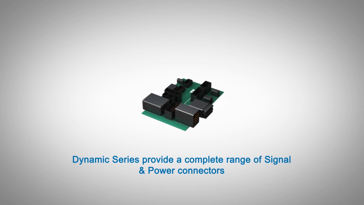
- Board and signal connectors like TE’s Dynamic Mini series are needed to support internal PCB power and signal connectivity. These connectors include an audible positive latching mechanism to facilitate installation and maintenance in the field. They are rated for operation from -40 to 125 °C to support the demands of AC charging installations. For example, model 1-2834461-2 has 12 positions on a 0.071-inch (1.8 mm) centerline.
- Power resistors are important for monitoring, managing, and ensuring safe operation. They must have high insulation resistance, low TCRs like 300 ppm/°C, low surface temperature rise, and fireproof construction. TE’s SQ series, like the 1 Ω ±5% 5W model SQPW51R0J, are suited for use in AC chargers.
- An emergency stop switch is important to AC charger safety. TE offers the PBE16 series pushbutton emergency stop switch in illuminated and non-illuminated versions. These switches meet IEC 60947-5-1 and IEC 60947-5-5 requirements. For example, model PBES16L1CR is IP 65 rated with a 20 Newton (N) actuation force to avoid unintended actuation.
- EMI filters are needed for the auxiliary power supplies in charging stations to prevent interference with the operation of the digital circuits used for power monitoring and control. Auxiliary power supplies are also needed to drive power for the power semiconductors in the power conversion section. TE’s model 6609065-3 is a single-phase EMI filter rated for 6 A at 250 Vac and 50 or 60 Hz.
- Finally, electrical solutions are needed for wiring and panel identification to speed assembly and maintenance in the field. These labels must be easy to install and highly durable. For example, TE’s PL-027008-2.5-9 is a polyester adhesive label designed for use in electrical cabinets like EV charging stations.
 Figure 3: Key components needed for Level 2 and Mode 3 AC chargers. (Image source: TE Connectivity)
Fast and XFC DC
From a high level, the types of components needed for Level 2 and Mode 3 AC chargers seem similar to those used in fast DC chargers.. However, there are some subtle and obvious differences between the two.
AC charging stations typically use relays for power control, while DC chargers need contactors. Although relays and contactors are both switches that use a low voltage like 12 Vdc to switch a higher voltage circuit, The devices use different contact structures optimized for different voltage and current levels. Relays are typically rated for up to 600 V, while contactors are rated for 800 V and higher. In addition, relays are typically limited to tens of amps, while contactors are available that can switch hundreds of amps. For example, TE’s EV200AAANA contactor is rated for 900 V and 500 A, and is suitable for fast DC chargers.
The signal connectors and power resistors used in DC chargers are not the same as those used in AC designs. DC chargers involve more complex control such as communications with the EV battery pack absent in AC designs. Both AC and DC chargers benefit from using board-to-board fine pitch connectors with a 0.050” x 0.050” (1.00 mm x 1.00 mm) centerline, but DC chargers can require higher pin counts like the 30 position 1MM-R-D15-VS-00-F-TBP.
In addition, the higher power levels in DC chargers can benefit from aluminum-housed power resistors like the HS series from TE. These wirewound resistors are very stable and can dissipate high power in a restricted space with relatively low surface temperature. For example, model HSA1010RJ is rated for 10 Ω ±5% and 10 W. Other models in the series are rated for up to 82 kΩ and up to 300 W.
Although the same type of emergency shut-off switch can often be used for AC and DC chargers, in the case of EMI filters, DC chargers may need larger filters or more filters depending on the design.
Another difference between AC and DC chargers is that DC chargers require power terminal blocks like TE’s ENTRELEC Compact Power Blocks for internal power distribution. The model CBS50-2P is rated for 150 A and 1 kV.
 Figure 4: Fast DC chargers need many of the same components as Level 2 and Mode 3 AC chargers, but there are also some subtle differences. (Image source: TE Connectivity)
Conclusion
Advanced EV charger designs will be critical in reducing range anxiety and enabling the large-scale deployment of EVs. These advanced chargers will use higher voltages and currents to reduce charging times to about 10 minutes, making EV charging comparable with the refueling times for ICE vehicles. As shown, designers need a wide array of compact, efficient, and environmentally rugged components for fast AC and DC chargers and future generations of XFC designs.
Disclaimer: The opinions, beliefs, and viewpoints expressed by the various authors and/or forum participants on this website do not necessarily reflect the opinions, beliefs, and viewpoints of DigiKey or official policies of DigiKey.