How to Optimize BLDC Motor Drive Thermal Performance in Challenging Environments
Contributed By DigiKey's North American Editors
2023-05-04
Brushless direct current (BLDC) motors are increasingly being used under demanding thermal conditions in automotive environments like electric vehicles (EVs), and in industrial applications like robotics and manufacturing equipment. For designers, effective thermal management is a key consideration to ensure the reliable operation of BLDC motor drives. To this end, they need to pay particular attention to the power MOSFETs and gate driver ICs with respect to switching frequency, efficiency, operating temperature range, and form factor, while also ensuring they meet qualifications such as AEC-Q101, Production Part Approval Process (PPAP), and International Automotive Task Force (IATF) standard 16949:2016, where applicable.
In addition, the gate drivers should be compatible with standard transistor-transistor-logic (TTL) and CMOS voltage levels to simplify interfacing with microcontrollers (MCUs). They also need to be able to protect the MOSFETs from various fault conditions, and they need to have well-matched propagation delays to support efficient high-frequency operation.
To meet these needs, designers can pair dual N-channel enhancement mode MOSFETs with high-frequency gate-driver ICs to produce compact, efficient solutions.
This article begins with an overview of thermal management considerations when designing BLDC motor drives, and then briefly summarizes the requirements of AEC-Q101, PPAP, and IATF 16949:2016. It then presents examples of high-performance dual N-channel enhancement mode MOSFETs and matching gate driver ICs from Diodes, Inc. that are suitable for automotive and industrial BLDC motor drive systems. The article closes with a discussion of pc board layout considerations for BLDC drive circuits, including minimization of electromagnetic interference (EMI) and optimization of thermal performance.
BLDCs and commutation
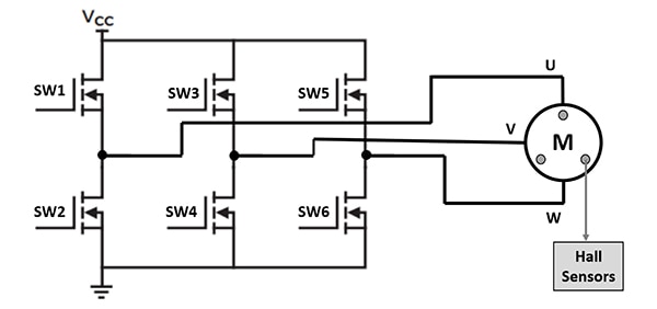
The key difference between BLDCs and brushed motors is that MCU control is needed with BLDCs to achieve commutation. This requires the ability to detect the rotational position of the rotor. Position detection can be accomplished using current-sense resistors or Hall effect sensors. Placing Hall effect sensors inside the motor—separated by 120°—is a common, accurate, and efficient way to implement position sensing.
The method involves the use of a bridge configuration of six power MOSFETs to drive a three-phase BLDC motor. The Hall effect sensors produce digital signals that the MCU uses to determine the position of the motor, and then produce the drive signals to switch the MOSFETs in the required sequence and at the desired rate to control the motor operation (Figure 1). Controllability is a key benefit of using BLDC motors.
 Figure 1: In a three-phase BLDC motor, three Hall effect sensors provide the position information needed to control the switching of the six power MOSFETs. (Image source: Diodes, Inc.)
Dealing with propagation delay
The control signals produced by the MCU are too weak to directly drive the power MOSFETs, so a gate driver IC is used to amplify the MCU signals. However, the introduction of the gate driver IC also introduces some amount of propagation delay of the control signals. In addition, the two channels in a half-bridge gate driver have slightly different response times that result in a propagation delay skew. In a worst-case scenario, the high-side switch can be turned on before the low-side switch is completely off, resulting in both switches conducting at the same time. If this occurs, there will be a short circuit, and the motor drive or motor can be damaged or destroyed.
There are a couple of ways to deal with propagation delay issues. One involves the use of a fast MCU that can react quickly enough to compensate for the propagation delay. Two potential problems with that approach are that it requires a more expensive MCU, and the MCU introduces a dead-time band into the switching process to ensure that the two switches are never on at the same time. This dead time delays the overall switching process.
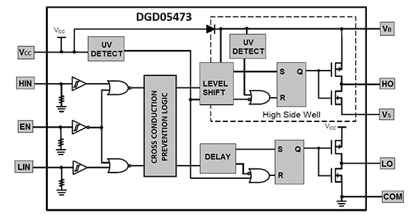
The preferred alternative in most applications is to use a gate driver with a short propagation delay. High-performance gate driver ICs also include cross-conduction prevention logic to further enhance system reliability (Figure 2).
 Figure 2: High-performance gate driver ICs include cross-conduction prevention logic (center left) in addition to having minimal propagation delays. (Image source: Diodes, Inc.)
Keeping cool
Safe and precise driving of the power MOSFETs is critical to the reliable operation of BLDC motors, as is keeping the power MOSFETs cool. Two important specifications related to thermal management for power semiconductors are the junction-to-case thermal resistance (RθJC), and the junction-to-ambient thermal resistance (RθJA). Both are expressed in degrees Celsius per watt (°C/W). RθJC is device and package specific. It is a fixed amount that depends on factors like die size, die-attach material, and package thermal characteristics.
RθJA is a more expansive concept: it includes RθJC plus the solder joint and heatsink temperature coefficients. For power MOSFETs, RθJA can be 10x larger than RθJC. Keeping the MOSFET package (case) temperature (TC) under control is a key consideration (Figure 3). This means factors like board layout and heatsinking are very important when developing a thermal management solution for power MOSFETs. Almost all the heat generated in the MOSFET will be dissipated through the copper pad/heatsink on the pc board.
 Figure 3: RθJA is a key metric of thermal dissipation and can be a 10x larger than RθJC. (Image source: Diodes, Inc.)
Automotive standards
To be used in an automotive application, the devices must also meet one or more industry standards, including AEC-Q100, AEC-Q101, PPAP, and IATF 16949:2016. AEC-Q100 and AEC-Q101 are reliability standards for semiconductor devices used in automotive applications. PAPP is a documentation and tracking standard, and IATF 16949:2016 is an ISO 9001-based quality standard. More specifically:
AEC-Q100 is a failure-mechanism-based stress test for packaged ICs and includes four ambient operating temperature ranges, or grades:
- Grade 0: -40°C to +150°C
- Grade 1: -40°C to +125°C
- Grade 2: -40°C to +105°C
- Grade 3: -40°C to +85°C
AEC-Q101 defines minimum stress-test-driven requirements and conditions for discrete devices like power MOSFETs and specifies operation from -40°C to +125°C.
PPAP is an 18-step approval process for new or revised components. It’s designed to ensure that components consistently meet specified requirements. PPAP has five standard levels of submission, and the requirements are negotiated between the supplier and customer.
IATF 16949:2016 is an automotive quality system based on ISO 9001, and customer-specific requirements from the automotive sector. This standard requires certification by a 3rd party auditor.
Dual power MOSFETs
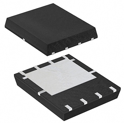
To implement an efficient BLDC motor drive, designers can use dual N-channel enhancement-mode FETs like Diodes Inc.’s DMTH6010LPD-13 for industrial applications, and the DMTH6010LPDQ-13 which is qualified to AEC-Q101 for automotive applications. Both parts are supported by a PPAP and manufactured in IATF 16949 certified facilities. These MOSFETs feature a low input capacitance (Ciss) of 2615 picofarads (pF) to support fast switching speeds, and a low on resistance (RDS(on)) of 11 milliohms (mΩ) for high conversion efficiency, making them suited for high-frequency, high-efficiency applications. The devices have a 10-volt gate drive, are rated for operation to +175°C, and come in a 5-millimeter (mm) x 6 mm PowerDI5060-8 package with a large drain pad for high thermal dissipation (Figure 4). Thermal specifications include:
- Steady State RθJA of 53°C/W with the device mounted on FR-4 pc board with 2-ounce (oz) copper and with thermal vias to a bottom layer that comprises a 1 inch (in.) square copper plate
- RθJC of 4°C/W
- Rated to +175°C
 Figure 4: The DMTH6010LPD-13 and the DMTH6010LPDQ-13 use the large drain pad of their PowerDI5060-8 package to support high thermal dissipation. (Image source: Diodes, Inc.)
Dual MOSFET gate driver
To drive dual power MOSFETs, designers can use either of two half-bridge gate drivers: the DGD05473FN-7 for industrial applications, or the AEC-Q100 qualified DGD05473FNQ-7 for automotive systems. These drivers are also supported by a PPAP and manufactured in IATF 16949 certified facilities. The inputs are compatible with TTL and CMOS levels (down to 3.3 volts) to simplify connection with an MCU, and the floating high-side driver is rated for 50 volts. Protection functions include UVLO and cross-conduction prevention logic (see Figure 2 again). The integrated bootstrap diode helps to minimize pc board space. Other features include:
- 20 nanosecond (ns) propagation delay
- 5 ns maximum delay matching
- 1.5 ampere (A) source and 2.5 A sink maximum drive current
- Under 1 microampere (µA) standby current
- AEC-Q100 grade 1 operating temperature range of -40°C to +125°C
Thermal and EMI considerations
Board layout best practices using the MOSFETs and driver ICs detailed above should combine a compact design with the largest practical copper areas for the MOSFETs to ensure the best possible thermal dissipation. The compact design will minimize loop areas, while short wiring lengths will minimize EMI and reduce electromagnetic compatibility (EMC) concerns.
To further improve EMC and thermal performance, a solid internal ground plane and an additional power plane on the bottom should be included in the pc board. In addition, a separate internal layer should be used for signal lines.
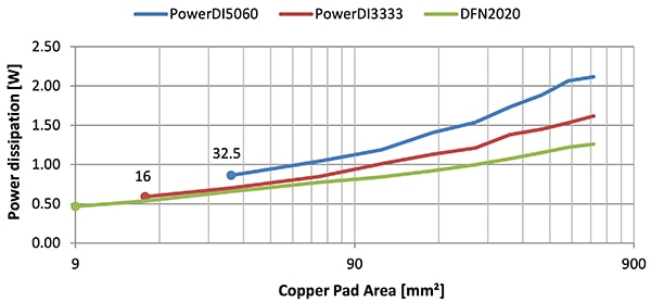
The MOSFET package has a major impact on thermal performance. Looking at three options, the PowerDI5060-8, the 3 mm x 3 mm PowerDI3333-8, and the 2 mm x 2 mm DFN2020-6, finds that the PowerDI5060 with the largest drain pad supports the highest power dissipation, reaching 2.12 watts (Figure 5).
 Figure 5: The PowerDI5060 (blue line) dissipates more power compared with the two smaller packages. (Image source: Diodes, Inc.)
Conclusion
Dual power MOSFETs in thermally efficient packages can be combined with matching gate drive ICs to produce high-performance and compact BLDC motor drives for automotive and industrial applications. These solutions can meet AEC, PPAP, and IATF standards for reliability, documentation, and quality, respectively. Using pc board layout best practices, the devices can be used to help designers arrive at the best thermal and EMC performance for their BLDC motor drive implementation.
Recommended reading

Disclaimer: The opinions, beliefs, and viewpoints expressed by the various authors and/or forum participants on this website do not necessarily reflect the opinions, beliefs, and viewpoints of DigiKey or official policies of DigiKey.


