How to Improve ESD Protection Using Transient Diverting Suppressors
Contributed By DigiKey's North American Editors
2022-08-10
The spread of Industry 4.0, the Industrial Internet of Things (IIoT), and 5G telephony are resulting in more sophisticated electronic devices being deployed in harsher and more inaccessible environments. This is contributing to the need for repeatable and deterministic protection from electrostatic discharge (ESD) and electrical overstress (EOS) events in applications such as industrial robots, IO-Link interfaces, industrial sensors and IIoT devices, programmable logic controllers (PLCs), and power over Ethernet (PoE). These applications are required to meet the transient protection requirements of IEC 61000. While transient voltage suppression (TVS) diodes have served designers well, increasingly, applications are requiring even more deterministic, linear, compact, and reliable ESD and EOS protection.
To address these rising performance and form factor demands, designers can turn to transient diverting suppressor (TDS) devices that combine superior clamping, linearity, and stability over temperature, for a more assured level of performance. Rather than dissipating surge energy like a TVS diode, a TDS device diverts surge energy to ground. Since they don’t dissipate the energy, TDS devices can be smaller compared with TVS alternatives, contributing to smaller solution sizes. Additionally, the clamping voltage of TDS devices can be 30% less than TVS diodes, reducing system stresses and improving reliability.
This article describes how TDS devices operate and the benefits they bring to key applications. It then introduces a variety of real-world TDS device examples from Semtech along with pc board layout guidelines for their successful application.
How TDS surge protection works
A surge-rated field effect transistor (FET) is the primary protection element in a TDS device. When an EOS event occurs and the transient voltage exceeds the breakdown voltage (VBR) of the integrated precision trigger circuit, the drive circuit is activated, turning on the FET which conducts the transient energy (IPP) to ground (Figure 1).
 activates the FET voltage-controlled switch (right)") Figure 1: In a TDS device, a precision trigger circuit (left) activates the FET voltage-controlled switch (right) when an EOS event is detected, diverting the energy spike (IPP) directly to ground (Image source: Semtech)
Figure 1: In a TDS device, a precision trigger circuit (left) activates the FET voltage-controlled switch (right) when an EOS event is detected, diverting the energy spike (IPP) directly to ground (Image source: Semtech)
As the pulse current rises toward IPP, the FET on resistance (RDS(ON)) becomes a few milliohms (mΩ), and the clamping voltage (VC) is nearly the same value as the VBR of the trigger circuit. As a result, the VC of a TDS device is almost constant across the IPP range. That differs from the clamping action in a TVS device, which is given as:
")
Where Rdyn is the dynamic resistance.
In a TVS device, Rdyn is a fixed value causing the clamping voltage to increase linearly with increases in IPP over the rated current range. For a TDS device, VC is stable over the operating temperature range, as well as the IPP range, resulting in deterministic EOS protection (Figure 2).
") Figure 2: The clamping voltage is constant across temperature and Ipp for a TDS device, such as the TDS2211P (solid line), providing deterministic EOS protection. (Image source: Semtech)
Figure 2: The clamping voltage is constant across temperature and Ipp for a TDS device, such as the TDS2211P (solid line), providing deterministic EOS protection. (Image source: Semtech)
The relatively low VC of TDS devices results in lower stresses on the protected components and improved reliability (Figure 3).
 of a TDS device (green trace)") Figure 3: The low VC (shown here as VClamp) of a TDS device (green trace) improves reliability by reducing the stress on the protected components. (Image source: Semtech)
Figure 3: The low VC (shown here as VClamp) of a TDS device (green trace) improves reliability by reducing the stress on the protected components. (Image source: Semtech)
TDS device performance supports the design of systems that meet the requirements of IEC 61000-4-2 for ESD immunity, IEC 61000-4-4 for burst/electrical fast transient (EFT) immunity, and IEC 61000-4-5 for surge immunity. This makes TDS devices suitable for use across a range of applications in harsh environments. The following sections present TDS application examples including a 22 volt TDS device for load switch protection, a 33 volt TDS device suited for IO-Link transceiver protection, and a 58 volt TDS device that can be used to protect PoE installations.
Protecting load switches
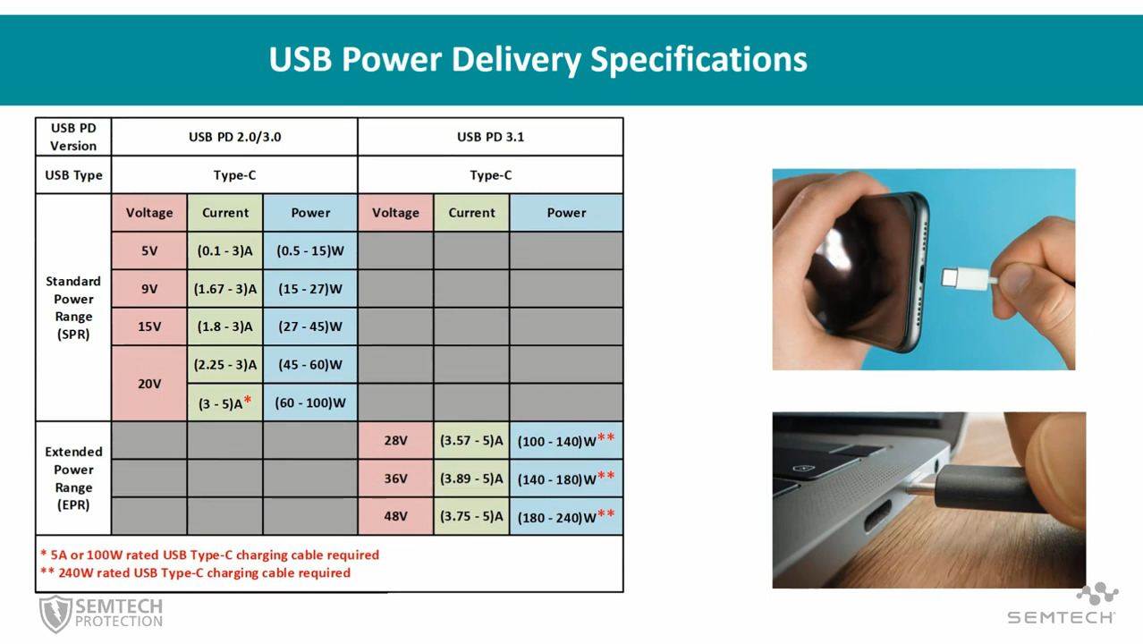
Load switches and e-fuse inputs in industrial equipment, robotics, remote meters, USB Power Delivery (PD), and IIoT devices can be protected from EOS events using the 22 volt TDS2211P. The EOS protection ratings of this TDS device include:
- ESD withstand voltage ratings of ±30 kilovolts (kV) for contact and air, per IEC 61000-4-2
- Peak pulse current rating of 40 amperes (A) (tp = 8/20 microseconds (μs)), per IEC 61000-4-5, and ±1 kV (tp = 1.2/50 μs; shunt resistance (RS) = 42 Ω), per IEC 61000-4-5 for unsymmetrical lines
- EFT withstand voltage of ±4 kV (100 kilohertz (kHz) and 5 kHz, 5/50 nanoseconds (ns)), per IEC 61000-4-4
When used in this configuration, the TDS2211P protects downstream components from lightning, ESD, and other EOS events, and it also keeps VC below the damage threshold of the switching FET in the load switch (Figure 4).
 (click to enlarge)") Figure 4: The TDS2211P can be used to protect a load switch (HS2950P) and downstream components from lightning, ESD, and other EOS events. (Image source: Semtech)
Figure 4: The TDS2211P can be used to protect a load switch (HS2950P) and downstream components from lightning, ESD, and other EOS events. (Image source: Semtech)
IO-Link protection
In addition to the general ESD and EOS hazards found in industrial environments, IO-Link transceivers can experience voltage spikes of several thousand volts when they are plugged in or unplugged from the IO-Link master device. The TVS diode typically used to protect IO-Link transceivers can be supplemented with TDS devices for improved protection. A typical circuit protection application uses devices rated for at least 115% of the input supply, so for a 24 volt application like IO-Link, a 33 volt protection device like the TDS3311P TDS is suitable. Key specifications of the TDS3311P include:
- ESD withstand voltage of ±30 kV for both contact and air, as required by IEC 61000-4-2
- Peak pulse current capability of 35 A (tp = 8/20 μs), and 1 kV (tp = 1.2/50 μs, RS = 42 Ω), as required by IEC 61000-4-5 for unsymmetrical lines
- Meets IEC 61000-4-4 for burst/EFT immunity
There are two common IO-Link port configurations, 3 pin and 4 pin, that require slightly different protection schemes. In both cases, the TDS devices can be supplemented with a µClamp3671P TVS diode on the VBUS (L+(24 volt)) line for reverse polarity protection (Figure 5).
") Figure 5: Comparison of ESD protection using TDS devices (green rectangles) for a 3 pin IO-Link port (top) and 4 pin IO-Link port (bottom). (Image source: Semtech)
Figure 5: Comparison of ESD protection using TDS devices (green rectangles) for a 3 pin IO-Link port (top) and 4 pin IO-Link port (bottom). (Image source: Semtech)
In the case of a 3-pin implementation, 3 TDS devices are required. If desired, bidirectional protection can be provided by the two TDS3311Ps facing each other. When a 4-pin configuration is used, all four pins of the IO-Link port should withstand both positive and negative surges. Testing to ensure the surge protection performance of IO-Link transceivers is needed between all pairs of pins on the connector and should be performed to the levels required by IEC 61000-4-2 for ESD, IEC 61000-4-4 for burst/EFT, and IEC 61000-4-5 for surges.
Protection for PoE
PoE protection schemes must consider the possibility that EOS events can be common mode (with respect to ground) or differential (line to line). PoE delivers power at 48 volts, so a 58 volt TDS device like the TDS5801P can be used to provide EOS protection on the RJ-45 connector side. Specifications for the TDS5801P include:
- ESD withstand voltage: ±15 kilovolts (kV) (contact) and ±20 kV (air) as needed for IEC 61000-4-2
- Peak pulse current capability: 20 A (tp = 8/20 μs), 1 kV (tp = 1.2/50 μs, RS = 42 Ω ) per IEC 61000-4-5
- EFT withstand voltage of ±4 kV (100 kHz and 5 kHz, 5/50 ns) as required by IEC 61000-4-4
Power in a PoE system is delivered using the center tap connections on the transformer. The PD (RJ-45) side must protect both Mode A (power delivered using data pairs 1 & 2 and 3 & 6) and Mode B (pins 4 & 5 and pins 7 & 8 deliver power), so two pairs of TDS5801Ps are required for bidirectional protection across the center tap connections (Figure 6).
 (click to enlarge)") Figure 6: Back-to-back TDS devices (green, TDS5801P) provide bidirectional protection from EOS events in a PoE system. (Image source: Semtech)
Figure 6: Back-to-back TDS devices (green, TDS5801P) provide bidirectional protection from EOS events in a PoE system. (Image source: Semtech)
Common mode isolation is provided by the transformer, but it does not protect from differential surges. During a differential EOS event, the transformer windings on the line side are charged and energy is transferred to the secondary side until the surge ends or the transformer saturates. The TDS devices on the PD side can be supplemented with four RClamp3361P ESD protection devices located on the Ethernet physical layer (PHY) side of the transformer to protect against differential EOS events.
TDS devices
SurgeSwitch TDS devices are available that offer designers a selection of operating voltages including, 22 volts (TDS2211P), 30 volts (TDS3011P), 33 volts (TDS3311P), 40 volts (TDS4001P), 45 volts (TDS4501P), and 58 volts (TDS5801P) (Table 1). They meet the requirements of IEC 61000 for use in systems that operate in harsh 5G telephony and industrial environments.
 Table 1: SurgeSwitch devices are available with voltage ratings from 22 to 58 volts for a range of application requirements. (Image source: Semtech)
Since TDS devices are non-dissipative and divert surge energy directly to ground through a low impedance path, they can be housed in a small 1.6 x 1.6 x 0.55 mm package that offers significant board savings over the SMA and SMB packages that are often used to house other surge protection devices. The 6 pin DFN package includes three input pins and 3 pins for diverting the surge energy to ground (Figure 7).
 Figure 7: TDS devices come in a DFN package measuring 1.6 x 1.6 x 0.55 mm with 6 leads (right); pins 1, 2, and 3 connect to ground, while pins 4, 5, and 6 are the EOS / ESD protection input. (Image source: Semtech)
Board layout guidelines
When placing a SurgeSwitch TDS device on a pc board, all the ground pins (1, 2, and 3) must be connected to a single trace, and all the input pins (4, 5, and 6) must be connected to a single trace for maximum surge current capability. If ground is on a different layer of the pc board, it is further recommended that multiple vias be used to connect with the ground plane (Figure 8). Following these pc board layout guidelines minimizes parasitic inductances and optimizes device performance. In addition, the SurgeSwitch TDS device should be placed as close as possible to the connector or device to be protected. This minimizes any coupling of transient energy to adjacent traces and is especially important during fast rise time EOS events. Since TDS devices do not dissipate any energy, there is no need for a thermal pad under the device to conduct away thermal energy.
 Figure 8: For optimal performance, connection with multiple vias is recommended when the ground plane is on a different layer of the pc board from the TDS device. (Image source: Semtech)
Conclusion
Designers of industrial and 5G telephony equipment that operates in harsh environments can turn to TDS devices to provide reliable and deterministic protection from ESD and EOS events. The relatively low VC of TDS devices increases system reliability by reducing component stresses. These devices meet the transient protection requirements of IEC 61000 and are available in a range of voltages from 22 to 58 volts to match the requirements of specific applications. Their compact size helps to reduce overall solution size, but designers need to follow some simple pc board layout requirements to realize the maximum performance from TDS devices.
Recommended Reading
Disclaimer: The opinions, beliefs, and viewpoints expressed by the various authors and/or forum participants on this website do not necessarily reflect the opinions, beliefs, and viewpoints of DigiKey or official policies of DigiKey.