How to Ensure Efficient and Stable DC Current for Green Hydrogen
Contributed By DigiKey's North American Editors
2024-07-30
The shift toward green hydrogen promises to reduce the level of greenhouse gases. Energy from renewable sources like hydroelectric, wind, and solar power, whether generated locally or transmitted via the power grid, must be converted efficiently to direct current (DC) to electrolyze water. For system designers, providing high and stable DC levels with low harmonic distortion, high current density, and good power factors (PFs) presents a challenge.
This article discusses the principle of green hydrogen. It then introduces power components from Infineon Technologies and shows how they can be used to convert the input from environmentally friendly energy sources into stable electrical power outputs with the characteristics required to generate green hydrogen.
Hydrogen generation by the electrolysis of water
Hydrogen can be separated from water by the process of electrolysis. The co-product of this process is oxygen. The electrolysis process requires the application of steady, high levels of DC. This process occurs in an electrolysis cell or electrolyzer that typically contains an anode (positive electrode) and a cathode (negative electrode) where the electrochemical reactions occur. A liquid or solid electrolyte encloses the electrodes and conducts the ions between them. A catalyst may be needed to increase the reaction rate depending on the process being used. The cell is powered by a steady, high-level DC source or power supply (Figure 1).
 Figure 1: A basic electrolysis cell separates water’s hydrogen and oxygen elements. (Image source: Art Pini)
The cell also includes a separator (not shown in this diagram) to prevent the hydrogen and oxygen produced at the electrodes from mixing.
The process requires high levels of DC. Under ideal conditions with no energy loss, a minimum of 32.9 kilowatt hours (kWh) of electrical energy is required to electrolyze enough water molecules to produce 1 kilogram (kg) of hydrogen. This will vary depending on the efficiency of the electrolysis process being used.
Three different processes are currently in use: alkaline electrolysis (AEL), proton exchange membrane (PEM), and solid oxide electrolysis.
The most established electrolyzers are AEL electrolyzers, which use an alkaline solution such as potassium hydroxide between the metal electrodes. They are less efficient than the other types of electrolyzers.
PEM electrolyzers use a solid polymer electrolyte enhanced with precious metal catalysts. They are characterized by higher efficiency, faster response times, and compact designs.
Solid oxide electrolyzer cells (SOECs) use a solid ceramic material as the electrolyte. They can be highly efficient, but they require high operating temperatures. Their response times are slower than the PEM electrolyzers.
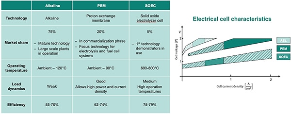
A comparison of the characteristics of the three techniques is shown in Figure 2.
 Figure 2: A comparison of the characteristics of the AEL, PEM, and SOEC processes highlights the improving efficiencies of the newer electrolyzers. (Image source: Infineon Technologies)
Green hydrogen generation currently costs more to produce than hydrogen from fossil fuels. This can be reversed by improving the efficiency of the discrete components, including the electrolyzers and power systems, and scaling up the conversion plants.
Power system configurations for grid and green power sources
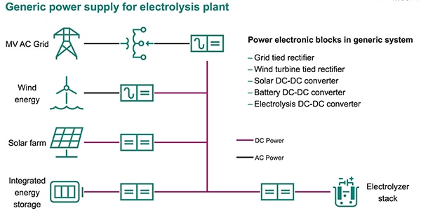
Currently, most hydrogen-generating plants are operating off the power grid. The power source for an electrolyzer is an AC to DC rectifier fed from a line transformer. Electrolysis plants powered from the grid must meet all grid standards and codes, such as achieving a unity PF and maintaining low harmonic distortion. Different power systems are required as green power sources are incorporated into the hydrogen separation process (Figure 3).
 Figure 3: Electrolysis plants must convert power from the source into DC for the electrolysis cells. (Image source: Infineon Technologies)
Like the power grid, wind-based power sources are AC, and powering electrolysis cells from them requires a rectifier to convert the AC into DC. Solar energy and hybrid sources using batteries rely on DC/DC converters to control the DC levels driving the electrolysis cells. The electrolysis cell may also employ a local DC/DC converter regardless of the power source. The electrolysis cell represents a constant DC load. Due to aging considerations within the electrolyzer cell, the applied voltage needs to increase over the cell's lifetime, so the power conversion system (PCS) should be able to accommodate that process. PCSs, whether mated to an AC or a DC source, will have some common specifications.
Their output voltage should be in the range of 400 VDC to 1,500 VDC). Alkaline cells have a maximum voltage range of approximately 800 V. PEM cells are not as limited and are moving toward the high end of the voltage range to lower losses and reduce costs. The output power range can be 20 kilowatts (kW) to 30 megawatts (MW). The current ripple from the PCS should be less than 5%, a specification still being studied for its effect on the cell’s lifetime and efficiency. PCS rectifier designs for power grid sources, especially for higher power loads, must comply with power companies’ large load and PF requirements.
Power conversion for AC sources
AC-powered hydrogen plants require a rectifier that may drive an electrolysis cell directly or may drive a DC grid attached to multiple cells.
A multi-pulse rectifier is a common choice (Figure 4). Thyristor-based, this rectifier design has high efficiency, is reliable, supports high current densities, and uses low-cost semiconductors.
 Figure 4: A multi-pulse rectifier based on thyristors has high efficiency, is reliable, supports high current densities, and uses low-cost semiconductors. Shown is a 12-pulse implementation. (Image source: Infineon Technologies)
Multi-pulse, thyristor-based converters are an established and well-known technology. The 12-pulse thyristor rectifier shown in Figure 4 consists of a wye-delta-wye power frequency transformer with two low-voltage secondary windings. The secondary windings drive two six-pulse thyristor rectifiers with their outputs connected in parallel. If this rectifier drives an electrolyzer directly, the thyristor firing angle controls the output voltage and the current flowing into it. The firing angle can also be used to maintain the current in the system as the electrolyzer cell ages, and the voltage required for the cell stack increases. The transformer may also include an on-load tap changer (OLTC). The OLTC changes the transformer turns ratio by switching among multiple access points or taps on one of the windings to raise or lower the voltage supplied to the rectifier.
Infineon Technologies offers a broad range of semiconductor component choices to PCS designers. Thyristor rectifiers are commonly used for these AC-source applications. For example, the T3800N18TOFVTXPSA1 is a discrete thyristor in a chassis mount TO-200AE disc package that is rated to handle 1800 V at 5970 amperes root mean square (Arms) on-state current. The disc package offers increased power density due to its double-sided cooling design.
The basic rectifier design can be improved by adding buck converters as post-rectification choppers at the rectifier output. Adding the chopper stage enhances control of the process by adjusting the chopper's duty cycle rather than the thyristor's firing angle (Figure 5). This reduces the dynamic range required for the thyristor, allowing optimization of the process.
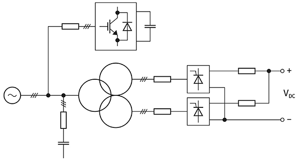
 Figure 5: A post-rectification chopper reduces current distortions and improves the PF. (Image source: Infineon Technologies)
Applying the post-rectification chopper using insulated gate bipolar transistors (IGBTs) eliminates the need for the OLTC transformer, reduces current distortions, and improves the PF.
Infineon Technologies’ FD450R12KE4PHOSA1 is an IGBT chopper module intended for these applications. It is rated for a maximum voltage of 1200 V and a maximum collector current of 450 A, and comes in a standard 62 millimeter (mm) C-series module.
More advanced rectifier circuits include IGBT-based active rectifiers. Active rectifiers replace diodes or thyristors with IGBTs that a controller switches on and off at appropriate times via a gate driver (Figure 6).
 Figure 6: An active rectifier replaces the diodes or thyristors in the rectifier circuit with IGBTs, which are switched by a gate driver controller. (Image source: Infineon Technologies)
Unlike a traditional rectifier, which produces non-sinusoidal line currents, an active rectifier has an inductor in series with the IGBTs that keeps the line current sinusoidal and reduces harmonics. The impedance of the IGBT when conducting is very low, which reduces conduction losses and improves efficiency compared to a standard rectifier. An active rectifier controller maintains a unity PF, so external power factor correction (PFC) devices are unnecessary. It also operates at higher switching frequencies, resulting in smaller-sized passive components and filters.
The FF1700XTR17IE5DBPSA1 combines dual IGBTs in a half-bridge configuration in a PrimePACK 3+ modular package. It is rated to handle 1700 V with a maximum collector current of 1700 A. The circuit shown in Figure 6 would use three such modules.
An IGBT gate driver such as the 1ED3124MU12HXUMA1 turns a single IGBT pair on and off. The gate driver is galvanically isolated using coreless transformer technology. It is compatible with IGBTs having voltage ratings from 600 to 2300 V, and has a typical output current of 14 A on separate source and sink pins. The input logic pins operate on a wide input voltage range from 3 to 15 V using CMOS threshold levels to support 3.3 V microcontrollers.
Power conversion for DC sources
Separating hydrogen using DC power sources such as photovoltaic energy and battery-based hybrid systems requires DC/DC converters. As noted earlier, these converters can improve the performance of diode/thyristor rectifiers. They also permit the optimization of local DC grids for plant flexibility.
The interleaved buck converter uses half-bridge chopper modules in parallel to change the DC level from the input to the output (Figure 7).
 Figure 7: An interleaved buck converter reduces the input DC level, VDC1, to the output level VDC2. (Image source: Infineon Technologies)
With proper interleave control, this DC/DC converter topology significantly reduces DC ripple without increasing the inductors' size or switching frequency. Each phase of the implementation can be realized with an appropriate module. The FF800R12KE7HPSA1 is a half-bridge IGBT 62 mm module suitable for the buck topology DC/DC converter. It is rated for a maximum voltage of 1200 V and supports a maximum collector current of 800 A.
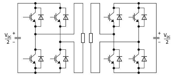
The dual active bridge (DAB) converter is an alternative to the buck converter (Figure 8).
 Figure 8: A DAB converter performs voltage step-down and provides galvanic isolation between input and output. (Image source: Infineon Technologies)
The DAB converter uses a high-frequency transformer to couple the input and output full-bridge circuits to provide galvanic isolation. Such isolation is often helpful to minimize corrosion of the tank and electrodes of the electrolyzer cell. Identical full-bridge circuits are driven with complementary square waves. The phasing of the drive signals between the primary side and the secondary determines the direction of power flow. In addition, the DAB converter minimizes switching losses by using zero-volt switching of the IGBTs. The circuit can be fabricated with half-bridge IGBT or silicon carbide (SiC) MOSFET modules.
Conclusion
As the worldwide demand for clean energy sources continues to increase, green hydrogen separation based on renewable energy sources will grow in importance. Such sources demand efficient, reliable, and highly stable DC power. Designers can turn to Infineon Technologies’ broad high voltage and current semiconductors portfolio for the necessary power conversion components.

Disclaimer: The opinions, beliefs, and viewpoints expressed by the various authors and/or forum participants on this website do not necessarily reflect the opinions, beliefs, and viewpoints of DigiKey or official policies of DigiKey.


