How to Ensure Automotive Safety Using High-Reliability Inductors
Contributed By DigiKey's North American Editors
2023-06-30
Advanced driver assistance systems (ADAS) and automated driving systems (ADS) are safety-critical automotive autonomous driving systems that comprise one or more advanced processors that make critical decisions based on the inputs of multiple sensors. These processors typically operate at various low voltage levels but may draw current in the double-digit ampere (A) range.
Power management integrated circuits (PMICs) are used to supply multiple voltages to the processors, but they require high-reliability inductors to ensure stable power. These inductors must be able to handle large currents with low power losses at power switching frequencies up to 10 megahertz (MHz). The inductors also need to be volumetrically efficient with a small, printed circuit (pc) board footprint and a low profile. Like all components in autonomous driving systems, they must meet the strict reliability and safety standards required by the automotive industry, such as AEC-Q200.
This article briefly describes the processing requirements of ADAS/ADS. It then introduces inductors from TDK that have been specially designed for this application and shows how their unique characteristics can help ensure a robust and safe automotive design.
Autonomous driving systems
A typical ADAS/ADS uses a specialized processor interfaced with multiple sensors to make the rapid decisions necessary for autonomous driving (Figure 1).
 Figure 1: The processor in an ADAS/ADS needs reliable low-voltage power at high current levels, which is supplied by a PMIC in order to control the vehicle based on sensor inputs. (Image source: EPCOS-TDK)
The power rail voltage for these processors is generally low, about 1 volt, but the current levels can be in the 10s of amperes, placing stress on the PMIC. The secondary converter in Figure 1 uses eight power inductors with the PMIC to supply power to the processor.
Power inductors are passive devices that store energy in their electromagnetic fields and are widely used in power supply circuits and DC/DC converters. Used with the PMIC as step-down or buck converters, the power inductors are key components that affect the performance of the power conversion process (Figure 2).
 Figure 2: A simplified schematic of a single buck converter highlights the role of the power inductor. (Image source: EPCOS-TDK)
A buck converter produces a lower output voltage than the input voltage. In a buck converter, a switch is placed in series with the input voltage source (VIN). The input source feeds the output through the switch and a low-pass filter. The filter is implemented with a power inductor and an output capacitor. In a steady state of operation when the switch is on for a period of TON, the input drives the output, as well as the power inductor. During this TON period, the difference in voltage levels between VIN and the output voltage (VOUT) is applied to the inductor in the forward direction, as shown by the ‘switch on’ arrow. The inductor current (IL) rises linearly to Ipeak.
When the switch is off (TOFF), the inductor current continues to flow in the same direction due to the stored energy from the inductor continuing to supply current to the load through the commutation diode, as illustrated by the ‘switch off’ arrow. During this TOFF period, the inductor has the output voltage VOUT applied across it in the reverse direction, and the inductor current decreases from the Ipeak value. This results in a triangular ripple current. The magnitude of the ripple current is related to the inductance of the power inductor. The value of the inductance is generally set to result in a ripple current of 20-30% of the rated output current. The output voltage will be proportional to the duty cycle of the switch.
If the load is increased suddenly, there will be a drop in output voltage, resulting in an abnormally large peak current through the power inductor over a short time to charge the output capacitor. The value of the power inductor affects the transient response of the converter: small inductor values speed recovery time and larger values increase the recovery time.
In the vehicle environment, these inductors must meet very high electrical and mechanical standards. The foremost of these is high reliability. The reliability and quality of passive components intended for operation in vehicles are qualified under standards set up by the Automotive Electronics Council (AEC). Passive components are qualified under AEC-Q200, the global standard for stress endurance that all passive electronic components must meet if they are intended for use within the automotive industry. The tests include resistance to shock, vibration, humidity, solvents, soldering heat, board flex, and electrostatic discharge (ESD). The tests also include temperature testing from -40°C to +125°C, with exposure to temperature extremes and thermal cycling.
For automotive applications, inductors must have compact dimensions and be able to operate over the expected automotive temperature range. The latter ability requires low series resistance to minimize power loss and minimize temperature rise. The inductors should also be able to operate at power switching frequencies in the range of 2 to 10 MHz that are typically used by PMICs, and also be able to handle high transient loads with the possibility of high saturation currents.
Power inductors designed for automotive
The CLT32 series power inductors from EPCOS-TDKare designed for ADAS/ADS applications and feature high reliability, high current ratings, low series resistance, high saturation currents, and small size (Figure 3).
 Figure 3: The TDK CLT32 series power inductors feature a single-piece coil/terminal structure that uses a thick copper winding with no internal connections. The magnetic molding material ensures a soft saturation characteristic. (Image source: EPCOS-TDK)
The CLT32 power inductors are formed around a one-piece, thick copper coil with an integral terminal structure. This means that there are no internal connections to cause unreliable operation. The thick copper coil also keeps the series resistance to as low as 0.39 milliohms (mΩ) to minimize power losses. The lower resistance also results in lower generated heat under load.
The coil is over-molded with a newly developed ferromagnetic plastic compound which forms both the coil’s core and outer housing. The core material has excellent electrical characteristics, even at high temperatures and in high-frequency applications. Of special note are the low core losses. Also, the material’s ability to be processed at low pressure and low temperature minimizes stress on the coil during production.
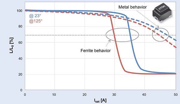
The core material provides a soft saturation characteristic compared with alternative ferrite materials. The change in inductance as a result of magnetic saturation is expressed as saturation drift, measured as the percentage change in inductance (Figure 4).
 Figure 4: In response to magnetic saturation, the CLT32 core exhibits low saturation drift, providing a soft response. (Image source: EPCOS-TDK)
The CLT32 core material provides noticeably lower change in inductance value due to saturation, especially at higher temperatures. They offer maximum saturation currents as high as 60 A.
The entire inductor fits in a low-profile package measuring 3.2 by 2.5 by 2.5 millimeters (mm). This high volumetric efficiency means multiple inductors can be used without having to move the design to a larger pc board. The inductors are rated to operate over a temperature range of -40°C to +165°C. This temperature range exceeds the requirements of the maximum AEC-Q200 test temperature of 125°C, mentioned above.
The TDK CLT32 power inductors are available in inductance values of from 17 to 440 nanohenries (nH), as shown in Table 1.
|
Table 1: Shown are the specified characteristics of the TDK CLT32 power inductors and their corresponding ordering code. All fit in the same 3.2 by 2.5 by 2.5 by 2.5 mm low-profile package. (Table source: EPCOS-TDK)
Referring to the Table, RDC is the series resistance of the inductor. Note that it scales with the inductance value due to the larger number of turns required for higher inductance. ISAT is the saturation current based on the reduction of the inductance value due to saturation, which scales inversely with inductance. Itemp is the maximum rated current, based on the temperature increase in the package. Itemp also scales inversely with the inductance value.
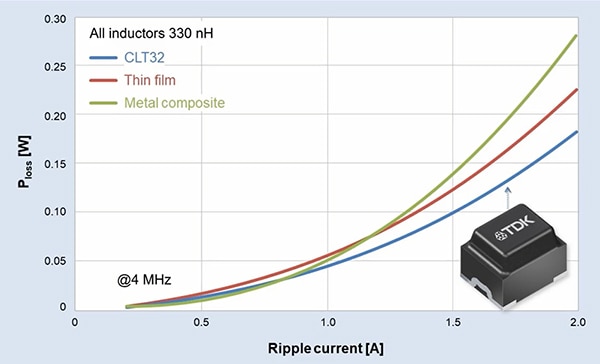
Losses in a power inductor include DC losses proportional to the series resistance of the coil. There are also AC losses due to the skin effect, hysteresis loss, and eddy current loss. The eddy current AC losses are related to the core material.
Compared to alternative technologies, like thin film or metal composite inductors, the CLT32 inductors show lower ripple current power loss (Figure 5).
 Figure 5: The CLT32 power inductors have lower ripple current power loss than thin film or metal composite inductor technologies. (Image source: EPCOS-TDK)
Low AC ripple losses mean that higher ripple currents can be tolerated, allowing lower capacitance values in DC/DC converters.
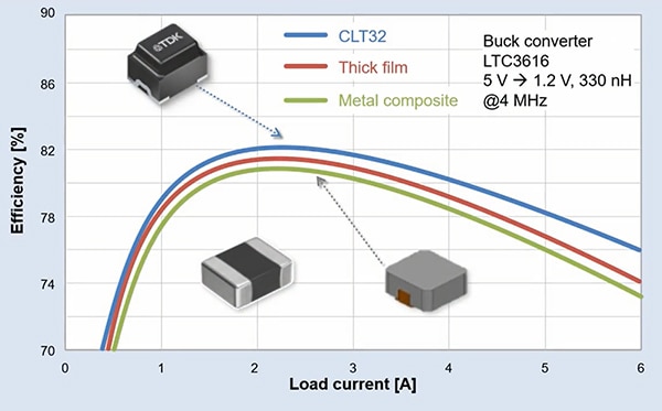
Lower losses also translate into higher efficiency compared to other inductor types (Figure 6).
 Figure 6: Performance comparison of power inductors in a single-output buck converter shows the higher efficiency of the CLT32 power inductors. (Image source: EPCOS-TDK)
Under light loads, core losses dominate the efficiency of the power inductor. Higher loading reduces efficiency due to resistive losses. In all cases, the CLT32 power inductors are better than the alternative technologies.
Conclusion
The innovative design concepts incorporated into the TDK CLT32 series power inductors offer smaller sizes and better electrical performance than competitive technologies while assuring higher reliability. Their wide temperature range and broad frequency range make them ideal components for use in next-generation ADAS/ADS designs.

Disclaimer: The opinions, beliefs, and viewpoints expressed by the various authors and/or forum participants on this website do not necessarily reflect the opinions, beliefs, and viewpoints of DigiKey or official policies of DigiKey.


