How to Develop Compact and Efficient Power Solutions for FPGAs
Contributed By DigiKey's North American Editors
2022-12-21
Field programmable gate arrays (FPGAs) are increasingly being used to support high-performance computing in video and image processing, medical systems, automotive and aerospace applications, and artificial intelligence (AI) and machine learning (ML). Powering an FPGA is a complex and critical function involving a large number and variety of power rails, with some needing up to 50 amperes (A), quickly.
For proper FPGA operation, power rails need on and off sequencing, they need to rise and fall monotonically, and they need high voltage accuracies and fast transient responses. In addition, the direct current to direct current (DC/DC) regulators that supply the various voltages need to be small so they can be placed near the FPGA to minimize parasitics in the power distribution lines, and they must be efficient to minimize temperature increases in the vicinity of the FPGA. In some systems, the DC/DC regulators must be thin enough to be mounted on the back side of the printed circuit board (pc board).
While it’s possible to design high-efficiency and high-performance DC/DC regulators with the necessary integrated digital power management, doing so in a very compact, low-profile format is a formidable challenge. It can result in numerous design iterations and become a distraction from designing the FPGA system, delaying time to market and reducing system performance.
FPGA power system designers can turn to fully tested and verified integrated DC/DC regulators that include all components in compact and thermally efficient land grid array (LGA) and ball grid array (BGA) packages, which are suited for integration directly adjacent to the FPGA to maximize power system (and FPGA) performance.
This article reviews the power delivery needs of FPGAs with a focus on voltage accuracy, transient response, and voltage sequencing, as well as detailing the challenges related to thermal management with operating examples. It then presents integrated DC/DC regulators suited for FPGA powering from Analog Devices, including low-profile regulators that can be mounted on the backside of the pc board, along with evaluation boards and integration suggestions to accelerate the design process.
FPGA power requirements
Functions within FPGAs like the core logic, input/output (I/O) circuits, auxiliary circuitry, and transceivers require different power rails. These are usually supplied using a distributed power architecture with one or more DC/DC regulators, also called point-of-load (POL) regulators, for each power rail. While most of these regulators use switch-mode power conversion for maximum efficiency, noise sensitive circuitry—such as transceivers—can require the use of low-dropout linear (LDO) regulators.
In small systems, the bulk power distribution voltage is usually 5 or 12 volts DC (VDC) which can directly power the POLs. In larger systems, the distribution voltage can be 24 or 48 VDC. When higher distribution voltages are used, a step-down regulator is used to drop the distribution voltage to 5 or 12 VDC on an intermediate voltage bus that powers the POLs. The POLs provide the low voltages required by the individual FPGA power rails (Figure 1). Each power rail has specific requirements related to accuracy, transient response, sequencing, and other parameters.
 Figure 1: Multiple POL regulators are needed to power an FPGA. (Image source: Analog Devices)
The core POL is usually the most critical power source in an FPGA. Core power can be below 1 VDC with tens of amps of current, and often has an accuracy requirement of ±3% or better to prevent logic errors. For example, for an FPGA with a ±3% core voltage tolerance specification, a regulator with a ±1.5% accuracy, provides another ±1.5% for transients. If the POL has good transient response, that will provide solid performance. However, a regulator with a ±2% accuracy can make it challenging to achieve the needed performance. There’s only ±1% available for transient response, requiring the addition of bypass capacitors and potentially leading to logic errors during transients.
The ups and downs of sequencing
In addition to demanding power requirements while they are operating, FPGAs need the various power rails to turn on and off in specific sequences with precise timing. Modern FPGAs often have numerous power rails organized into a few groups that can be turned on and off together. For example, Altera Arria 10 FPGAs from Intel have power domains organized into three groups. These groups must power up in order from Group 1 (with six voltage rails) to Group 2 (also six voltage rails) to Group 3 (three rails), and power down in the reverse sequence to prevent damage to the FPGA (Figure 2).
 Figure 2: FPGAs require that power rails be powered up and down in a specific sequence. (Image source: Analog Devices)
Keeping it cool
With so many regulators placed close to the FPGA, thermal management is a concern. Analog Devices has put together a pc board to demonstrate some thermal management options when using multiple regulators (Figure 3). Thermal performance is impacted by the relative placement of the regulators, the direction and amount of airflow, and the ambient temperature.
 Figure 3: Thermal management demo board for paralleled regulators. (Image source: Analog Devices)
For the first comparison, the temperature is measured at seven locations on the demo board; locations 1 to 4 show the surface temperature of the modules and locations 5 to 7 show the surface temperature on the pc board (Figure 4). In both thermographs, the outside modules are cooler, benefiting from the increased heatsinking provided by using the pc board area on three sides, compared to the center modules that only dissipate heat on two sides. Airflow is also important. In the left-hand thermograph, there is 200 linear feet per minute (LFM) of airflow coming from the bottom of the pc board, compared with no airflow in the right-hand image. The modules and pc board with airflow are about 20°C cooler.
") Figure 4: Adding airflow of 200 LFM significantly reduces module and pc board temperatures (left). (Image source: Analog Devices)
Figure 4: Adding airflow of 200 LFM significantly reduces module and pc board temperatures (left). (Image source: Analog Devices)
The direction of airflow and ambient temperature are also important. Using 400 LFM airflow from right to left pushes the heat from one module to another, with the result that the coolest module is on the right, the center modules are the hottest, and the module on the left is in between (Figure 5, left). To try and compensate for the higher ambient temperature, heatsinks have been placed on the modules operating at 75°C. Under this extreme condition, the modules are significantly hotter, even with the additional heatsinking (Figure 5, right).
 and 75°C (right) ambient temperatures (click to enlarge)") Figure 5: The impact of 50°C (left) and 75°C (right) ambient temperatures with 400 LFM airflow from right to left across the pc board. (Image source: Analog Devices)
Figure 5: The impact of 50°C (left) and 75°C (right) ambient temperatures with 400 LFM airflow from right to left across the pc board. (Image source: Analog Devices)
LGA and BGA packages for backside mounting
The LTM4601 family of 12 A continuous (14 A peak) step-down DC/DC regulators provides designers with the option of a 15 × 15 × 2.82 millimeters (mm) LGA or a 15 × 15 × 3.42 mm BGA package. They have an input voltage range of 4.5 to 20 VDC and can provide outputs from 0.6 to 5 VDC with output voltage tracking and margining. They feature ±1.5% regulation and a peak deviation of 35 mV for dynamic load changes from 0% to 50% and 50% to 0% of full load, with a settling time of 25 microseconds (µs).
These regulators are available with and without an onboard differential remote sense amplifier that can be used to accurately regulate an output voltage independent of load current. For example, the LTM4601IV#PBF is in an LGA, and the LTM4601IY#PBF is in a BGA, and both have an onboard differential remote sense amplifier. Applications that don’t need the onboard amplifier can use the LTM4601IV-1#PBF in an LGA or the LTM4601IY-1#PBF in a BGA. These modules are complete DC/DC regulators, needing only input and output capacitors to suit specific design requirements (Figure 6). The low profile of these modules enables them to be mounted on the back side of the pc board.
 Figure 6: μModule regulators are complete power converters in thermally enhanced packages. (Image source: Analog Devices)
Analog Devices offers the DC1041A-A demonstration circuit to speed evaluation of LTM4601 regulators. It has an input voltage range of 4.5 to 20 VDC, and an output voltage that is jumper selectable as well as programmable to ramp up and down coincidentally or ratiometrically tracking the output of another module.
Ultra-thin regulators
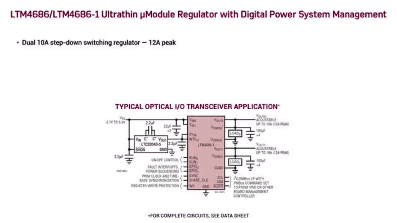
The 1.82 mm height of the 16 × 11.9 mm LGA package of Analog Devices’ LTM4686 enables these dual 10 A or single 20 A regulators to be placed close enough to an FPGA that the devices can share a common heatsink, simplifying thermal management. In addition, these regulators fit on the backside of the pc board. Integrated digital power management using the PMBus protocol supports remote configuration and real-time monitoring of output current, voltage, temperature, and other parameters. These regulators are available to support two input voltage ranges; the LTM4686IV#PBF operates from 4.5 to 17 VDC, and the LTM4686IV-1#PBF from 2.375 to 17 VDC. LTM4686 modules support outputs from 0.5 to 3.6 VDC with ±0.5% maximum output error. These regulators can deliver 18 A at 1 VDC from a 5 VDC input at +85°C ambient with 400 LFM airflow.
Designers can use the DC2722A demonstration circuit combined with the LTpowerPlay software to explore the capabilities of LTM4686 modules. To evaluate just the regulator, the DC2722A can be turned on using the default settings without the need for PMBus communication. Adding the software and the PMBus dongle enables designers to explore the complete digital power management capabilities, including reconfiguring the part on the fly and viewing telemetry information.
Board layout considerations
While there are few electrical considerations when paralleling μModule regulators to power FPGAs, parameters related to spacing, vias, ground planes and airflow are important. Fortunately, the design of the LGA footprint simplifies the layout of power and ground planes and provides a solid thermal connection to the pc board. Placing four parallel μModule regulators is a simple matter of repeating the LGA footprint (Figure 7). Except for unusually challenging environments, the thermally enhanced package, along with the power plane, typically provides adequate cooling for the modules.
 Figure 7: The LGA footprint of μModule regulators simplifies paralleling of multiple modules and supports enhanced thermal performance. (Image source: Analog Devices)
Conclusion
To support high-performance computing applications, FPGAs require precise and efficient power management with a fast response time. Powering the numerous voltage rails in an FPGA is a complex challenge that can be met using integrated μModule DC/DC regulators from Analog Devices. These regulators also provide the electrical and thermal performance needed in compact and easily integrated packages.
Disclaimer: The opinions, beliefs, and viewpoints expressed by the various authors and/or forum participants on this website do not necessarily reflect the opinions, beliefs, and viewpoints of DigiKey or official policies of DigiKey.