Handling Voltage Swings in IIoT Designs
Contributed By DigiKey's European Editors
2016-03-17
The electronics for many industrial control systems have traditionally been built into cabinets that use the DIN-rail mounting system for ease of design, integration and maintenance. There is a wide range of standard power supplies, enclosures and other products that fit the DIN-rail format. This availability reduces the time it takes to select, qualify and build the final system.
The trend towards the Industrial Internet of Things (IIoT) calls for greater levels of distributed control. Intelligence will be devolved to processors that, for reasons of responsiveness and flexibility, can be mounted very close to the actual sensors and actuators. The processors communicate through a combination of wired and wireless networks, reducing the need for cooperating processors to coexist within a single enclosure where previously they would traditionally share data across a PCB or backplane bus.
Although the target system may be designed to fit onto a DIN rail for ease of mounting, each unit will be much smaller and call for an individual power supply rather than a power rail shared within a larger cabinet. Because it provides a safe voltage level for many environments and retains compatibility with existing environments, 24 VDC is likely to remain in common use as a rail supplying electronic controllers in both discrete and cabinet-housed equipment.
The nature of the industrial environment means the controllers' power supplies will still have to cope with large variations in input-voltage ranges due to induced voltages and noise caused by nearby equipment or intermittently heavy loads with large inductive and capacitive elements. What is required is a power source that is compact and able to deliver reliable energy over fluctuations in input voltage and over large changes in load consumption. Many electronic controllers will power down into a sleep mode when not active to conserve energy. The power supply also needs to be able to react to those situations efficiently.
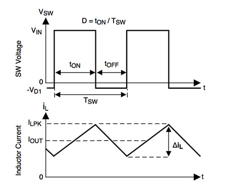
A regulator such as the LM43603 regulator made by Texas Instruments or the LTM8025 from Linear Technology provides the ability to switch between continuous conduction mode (CCM) and discontinuous conduction mode (DCM) to cater for changes in power consumption and to support changes in input voltage. With CCM, the current in the inductor, which is used to help smooth the delivery of current to the load, always stays above zero during any part of the switching cycle. In DCM, the current in the inductor is allowed to fall to zero. The amount of current delivered to the inductor by a pair of FET switches in the converter during each cycle is determined using pulse width modulation (PWM).

Figure 1: Inductor current in continuous conduction mode for a PWM-controlled switched-mode regulator.
On each cycle, the converter supplies a regulated output voltage by first turning on the high-side FET switch for a certain amount of time. During this on-time, the output voltage swings up towards the input voltage and the current flowing into the inductor starts to rise with a linear slope given by the formula (Vin - Vout)/L.
When the control logic decides to switch off the high-side switch in order to regulate the voltage and prevent it from continuing to climb towards the input level, the low-side switch is kept off to prevent shoot-through for a short period and then allowed to switch on. The inductor current then begins to fall with a slope of -Vout/L.
The PWM controller inside the converter samples the output voltage and compares this to a reference voltage to generate an error signal that is used to calculate the duty cycle for the two phases. In an ideal converter design, the duty cycle is proportional to the output voltage. An error amplifier ensures that the DC/DC converter adjusts the duty cycle to preserve a regulated output voltage.
The error signal generated by the amplifier will generally be very close to zero at any point in time as the changes in input voltage and output demand will generally be slower than the switching rate of the power supply controller. The adaptation functionality that PWM provides lets the strategy compensate for swings on the input rail without affecting the supply of energy to the load.
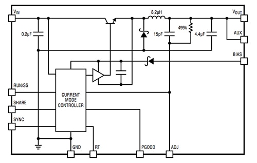
The use of high frequency switching allows the LM43603 to operate from a supply voltage that ranges from 3.5 V to 36 VDC and is capable of delivering up to 3 ADC load current with high efficiency and good thermal performance in a small solution size. The switching frequency is programmable from 200 kHz to 2.2 MHz through the use of a programmable resistor connected to the RT signal that feeds into the oscillator module within the LM43603 controller. Its standard frequency without the use of an external resistor is 500 kHz. The LTM8025 operates over a frequency range of 200 kHz to 2.4 MHz and is similarly programmed using a resistor with one terminal connected to the RT pin and the other to ground.

Figure 2: Block diagram of the LM43603.
Under light loads, the efficiency of PWM-controlled CCM regulation drops off significantly. DCM provides the ability to improve efficiency by disconnecting the load from the input for longer periods of time, during which time the inductor current is allowed to fall to zero. Output capacitors help minimize the effects of ripple in this mode.
In the case of the LM43603, the converter will move into DCM when the load current is less than half the peak-to-peak inductor current ripple in CCM. Switching losses are reduced by turning off the low-side FET at zero current. During DCM, switching frequency reduces. The converter turns on the high-side FET when the sampled output voltage falls below an acceptable value.
Devices such as the LM43603 and the LTM8025 offer stable operation with most capacitor forms on the input and output. Because of their compact size, ceramic capacitors are often favored, as the capacitance requirements are generally below 100 µF for high-frequency operation and typical mixed-signal circuit voltages of 3 to 12 VDC. Ceramic capacitors are small, robust and have very low ESR. However, not all ceramic capacitors are suitable. X5R and X7R types are stable over temperature and applied voltage but, in contrast, Y5V and Z5U have very large temperature and voltage coefficients of capacitance. In use, they may exhibit only a small fraction of their nominal capacitance resulting in much higher output voltage ripple than expected.

Figure 3: Block diagram of the LTM8025.
Ceramic capacitors are also piezoelectric. In DCM or burst mode, the switching frequency will depend on the load current, and can excite a ceramic capacitor in the audio frequency range, generating audible noise. Because the currents generated in DCM conditions are lower, the noise is typically low but, if audible noise is unacceptable, a high performance electrolytic capacitor may be more suitable. Alternatively, the parallel combination of a ceramic capacitor and a low-cost electrolytic capacitor could be used.
Soft-start capability is another important consideration. The LM43603, for example, has a soft-start control pin: SS/TRK. Use of the pin forces the regulator, once an input voltage has been applied, to slowly ramp up the output voltage over a period of time. If the SS/TRK pin is left floating, the LM43603 will use its own ramp period controller to let the output voltage move up to full output in just over 4 ms.
For applications that employ a large amount of output capacitance, or for systems that use relatively high output voltages, the start time can be extended by connecting an external capacitor between the SS/TRK pin and the device’s analog ground reference pin (AGND). The capacitance value determines the ramp period. Alternatively, the soft-start controller can track an external ramp signal using a resistor-divider pair and an external voltage source that describes the desired ramp profile.
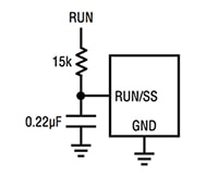
Control over soft-start for the LTM8025 is performed using a capacitor connected to the RUN/SS pin and ground together with a connection to an external voltage source through a resistor. The resulting RC time constant determines the soft-start timing.

Figure 4: Connections for an external ramp signal to soft-start the LM43603.

Figure 5: Connections for generating a soft-start ramp for the LTM8025.
As IIoT power controllers need to fit into a small space and be easily integrated with industrial equipment, electromagnetic compatibility (EMC) is an important consideration. The key to ensuring that any electromagnetic interference (EMI) generated by a switched-mode power regulator is to keep any di/dt loops as small as possible. This is enabled to a large degree by the high levels of integration offered by devices such as the LM43603 and LTM8025.

Figure 6: The key di/dt loop for a switched-mode buck converter.
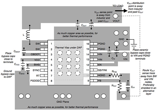
However, care needs to be taken in the placement of external devices, particularly any feedback nodes. Traces to external resistors and bypass capacitors should be kept as short as possible. Any long PCB traces that lead to resistors can result in excessive EMI being generated. Shielding is also important and this can be achieved to a high degree using additional ground planes within the PCB.
Through the use of high-integration regulators such as the LM43603 and LTM8025, designers of IIoT-oriented industrials controllers can ensure they can deliver DC power reliably and with confidence in the EMC of the final product.

Figure 7: Low-EMI layout recommendations for the LM43603.

Disclaimer: The opinions, beliefs, and viewpoints expressed by the various authors and/or forum participants on this website do not necessarily reflect the opinions, beliefs, and viewpoints of DigiKey or official policies of DigiKey.


