Differences Between 3D Printing with Carbon Fiber and Automated Carbon Fiber Layup
2023-03-09
In recent years, two developments have blurred the line between 3D printing and composite fabrication. The first development is the way in which 3D printing now allows the use of high-strength polymers such as nylon to act as a matrix with continuous carbon fibers reinforcing the printed components.
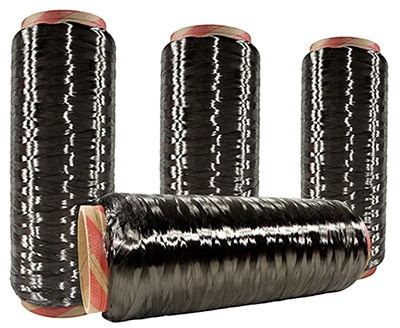
 Figure 1: These are bobbins of carbon fiber in a fiber-production facility. This material is used extensively for the reinforcement of workpieces made via additive-manufacturing methods. (Image source: Getty Images)
The second development is the way in which composite fabrication (especially for aerospace and automated machinery components) is increasingly migrating away from hand layup toward automated processes. The latter include automated tape laying and fiber placement relying on robotic automation to deposit the material.
In fact, there are still other differences between the two processes and the performance of the various carbon-fiber-reinforced plastic (CFRP) components that they produce.
Carbon-fiber-reinforced 3D printing
What almost all additive manufacturing (AM) processes have in common is that they build up a 3D component by laying down a series of two-dimensional layers — one on top of the other. There are many different AM processes; the two most well established for industrial applications are selective laser sintering (SLS) and stereolithography.
SLS uses lasers to fuse a powdered material layer by layer to build components. First developed for a buildup process tailored to polymers, today SLS is increasingly used to produce aluminum, stainless steel, and titanium aerospace components having high strength.
However, the AM process with which most laypersons (and engineers) are familiar is filament deposition modelling or FDM. In FDM layups, a spool of filament feeds into a heated subassembly and then exists a nozzle as molten polymer. The nozzle then travels the face of the part being built as the polymer material freely flows and deposits onto the present part layer (and quickly solidifies). The process is a bit like building up a 3D part using a hot-glue gun.
Today, low-cost FDM machines abound … which is in part why FDM is the AM subtype most people mean when referring to 3D printing. Although the terms 3D printing and additive manufacturing can be used interchangeably, the latter typically refers to high-quality industrial prototyping and production parts. In contrast, the term 3D printing more commonly (though not always) refers to low-cost prototyping and hobby-grade applications.
Some FDM machines are compatible with polymer materials that are reinforced with a relatively small percentage of short-strand randomly orientated glass or carbon fibers. Such types of reinforcement are more commonly associated with high-strength injection-molded components (such as automobile fenders and dashboards, for example) than high-performance composite components destined for inclusion in automated machinery. On the other hand, a select few advanced FDM machines today are capable of depositing high-strength polymers such as nylon together with continuous strands of carbon fiber. Markforged was an early pioneer of this kind of 3D printing to leverage the fortifying benefits of continuous-strand carbon fiber. No wonder this company remains the one most engineers associate with the production of components having such reinforcement.
Automated composite fabrication
Within industries such as aerospace, traditional composite fabrication based on manual operations are slowly being replaced with automated processes. Six-axis industrial robots as well as bespoke gantry machines are leading motion system designs to execute:
- Automated fiber placement and filament winding
- Resin infusion methods to inject resin into molds containing dry fiber preforms
Automated composite-injection processes are further differentiated as open mold and closed mold techniques. Closed-mold composite-injection processes ensure all external faces are smooth and well controlled. In contrast, open-mold processes have a well-controlled outer mold line surface and a much rougher inner mold line surface.
Automated tape laying or ATL machines typically use gantry machines to deposit so-called prepreg tape pre-impregnated with resin onto relatively flat or gently curved single-sided molds. The end effectors on ATL machines can include:
- Rollers
- Heating elements to debulk and tack plies as they are deposited
- Cutters to cut the tape before starting at a new position
Tapes are usually three to 12 millimeters wide but can be up to 300 mm with continuous fibers embedded in a thermoplastic or thermoset tape. Thermoset resins are typically cured in an autoclave after the ATL operation, while thermoplastic tapes require a pre-heater on the tape laying head. Multiple layers of tape are deposited on top of each other with excellent control over fiber orientation.
The ATL layup process achieves very high deposition rates — even to 45 kilograms per hour. The only catch is that it requires expensive prepreg materials.
Another technique called filament winding deposits fibers onto a rotating mandrel — a type of single-sided mold for the production of tubular structures. As the mandrel rotates, it pulls fibers from a spool … which in turn are moved up and down the axis of rotation to control the fiber orientation. Filament winding is compatible with both prepreg tape as well as dry fibers impregnated on the fly — just before deposition. With the latter, the dry fibers are drawn through a resin bath in a process called wet winding, which has the benefit of minimizing material costs. With filament winding, the profile of the workpieces being produced needn’t be perfectly circular but do need to be continuously convex. Tension in the fibers results in good compaction and a reasonably good control of fiber orientation — although control of the fibers’ axial alignment isn’t possible.
Narrow-tape automated fiber placement (AFP) and automated tow placement (ATP) processes are now widely used in aircraft production. With these approaches, an array of narrow prepreg tapes is simultaneously deposited on a workpiece build. AFP and ATP combine many of the advantages of filament winding and automated tape laying. However, they offer the additional benefit of much tighter curves than ATL processes while still maintaining a high deposition rate. Both fixed molds and rotating mandrels may be used.
Resin transfer molding or RTM is similar to injection molding. It uses a closed mold into which resin is injected, albeit at a much slower speed than injection molding. (Filling a mold with RTM can often take five to 20 minutes.) A dry-fiber preform must first be cut, assembled, and placed into the mold … and that’s usually performed by a six-axis robot receiving a significant amount of manual intervention. The benefit of RTM is that the additive process can achieve complex shapes with very tight tolerances.
Key process differences between 3D printing and automated composite fabrication
The most obvious and fundamental differences between 3D printing and automated composite fabrication relate to their tooling requirements.
3D printing simply builds up material on a flat baseplate, constructing its own support structures where required for overhanging or hollow structures. Therefore, it requires no part-specific tooling — allowing one-off designs to be rapidly constructed at low cost. In contrast, all automated composite fabrication processes deposit material onto some form of mold tooling, which defines the final form of the component. This means that expensive and time-consuming machining operations are typically required before the actual composite fabrication can even begin, making these methods much less suited to rapid and one-off prototyping.
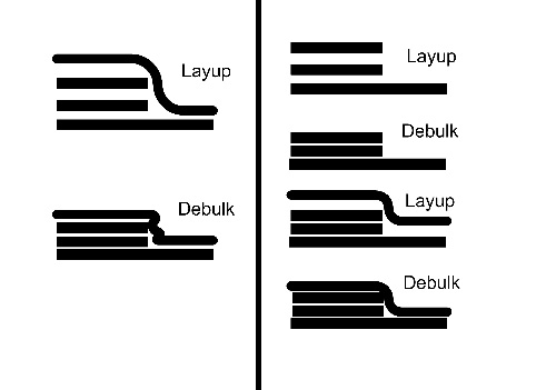
Additional differences between 3D printing and automated composite fabrication relate to their overall complexities. While 3D printing is essentially a single process (with a relatively modest amount of roughness removal and cleanup after material deposition) composite fabrication often involves several finishing processes. Components may be laid up on a mold with multiple compactions and debulking operations performed between layups … and subsequent autoclave curing may also be required. Although composite fabrication may result in higher performance workpieces, it also requires significantly more capital-intensive equipment and expertise.
 Figure 2: Note the differences between the debulking processes for 3D printing at left and automated composite fabrication at right. (Image source: Jody Muelaner)
Compaction or debulking operations are sometimes carried out using rollers or vacuum bags. Such techniques can improve fiber fraction and also prevent issues such as wrinkling. Consider the example below with an outer ply susceptible to wrinkle if the lower plies aren’t first debulked.
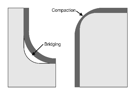
 Figure 3: Additive manufacturing issues include bridging and compaction. (Image source: Jody Muelaner)
Two problems can arise on the corners of additively manufactured workpieces: Bridging and compaction. Bridging affects internal radii where a ply may not fully conform to the mold or a previous ply resulting in a void. Compaction affects external radii and results from debulking and consolidation forces overly concentrated on reducing the material thickness at a workpiece’s corners.
Boosting carbon fiber-reinforced plastic performance
Reinforced workpieces made by additive manufacturing are essentially carbon fiber-reinforced plastic or CFRP pieces containing fibers bonded together by a polymer matrix. The strength of CFRP components isn’t limited by the strength of individual carbon fibers but rather by the:
- Percentage of the overall material content consisting of carbon fiber
- Exact subtype of fiber-matrix interface
- Fiber orientation
The fiber fraction is the percentage of carbon fibers in the overall mass of the component. Because it is the carbon fibers which largely give CFRP its strength, higher performance is achieved when the fiber fraction is very high … with just enough matrix material to efficiently hold the fibers together. However, there is a caveat to consider here.
The fiber-matrix interface is the bond between the surfaces of individual carbon fibers and the polymer matrix. It’s typically at these interfaces that failures actually occur. The first stage in achieving a good fiber-matrix interface is ensuring that fibers are fully wetted out during the formation of the composite material so that the polymer actually penetrates through to all of the fibers. Vacuum bagging and compaction can dramatically improve wetting out and the fiber fraction that can be achieved. The optimal fiber fraction is typically 55 to 65% as that range ensures complete wetting out. High fiber fractions are also possible using 3D printing.
The matrix material type also affects the fiber-matrix interface; autoclave-cured thermoset resins generally yield higher performance than thermoplastics.
Conclusion
Workpieces made by automated composite fabrication currently achieve much higher performance than 3D-printed parts containing carbon fiber … although there appears to be little fundamental reason for this. Modern thermoplastics can now achieve reasonably high performance and are increasingly common in the manufacture of automated aircraft parts and other exacting applications.
Soon, components made by 3D-printed processes incorporating carbon-fiber reinforcement could rival the performance of components fabricated via conventional thermoplastic-composite means. However, the precision surfaces and shapes possible with traditional sheet metal processing and machine-tool methods (as needed for tightly controlled mold lines, for example) is one area that 3D printing is unlikely to rival anytime soon.
Disclaimer: The opinions, beliefs, and viewpoints expressed by the various authors and/or forum participants on this website do not necessarily reflect the opinions, beliefs, and viewpoints of DigiKey or official policies of DigiKey.


