Design Considerations for High-Voltage DC/DC Modules
Contributed By DigiKey's North American Editors
2025-07-15
Selecting the right DC/DC converter is a critical design choice when applications require compact, isolated high-voltage power sources. The converters must ensure accurate, stable, and adjustable output voltages while withstanding various electrical and environmental stressors that can impact reliability and safety.
While the performance specs of a high-voltage DC/DC converter might look solid on paper, the real test begins once the module is integrated into a physical product—and deployed in the real world.
Understanding how to evaluate and integrate DC/DC converters will go a long way in determining success in prototyping and moving to production.
High-voltage DC/DC converters play a crucial role in applications such as analytical instruments, semiconductor processing, medical diagnostics, and scientific research. Integrating high-voltage modules into critical, long-term applications requires certain criteria:
- Mass spectrometry and electrophoresis require stable, low-noise high-voltage for accurate chemical separation and detection.
- Electrostatic chucks in wafer fabrication need precise voltage to hold silicon or glass substrates during processing.
- Scanning electron microscopes (SEMs) rely on ultra-stable bias for beam control and image clarity.
- Photomultiplier tubes (PMTs) demand stable bias and ripple-free voltage to avoid noise in measurements or photon detection.
- Capacitor-charging circuits benefit from the regulator’s fast current limiting and arc protection.
- Medical diagnostic tools use high-voltage modulators for analyte (target substance) detection or therapeutic control, demanding reliability and safety.
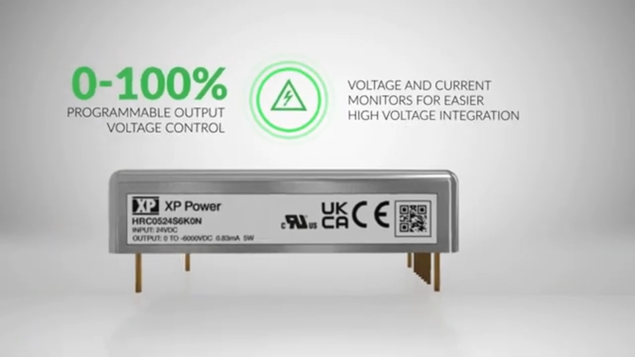
One leading solution is the HRC05 series (Figure 1) of high-voltage DC/DC converter modules from XP Power, which meet these demands with compact 5 W versions that balance regulation performance with ease of implementation.
 Figure 1: The form factor of the HRC05 series of regulated 5 W high-voltage DC/DC converters. (Image source: XP Power)
Module requirements
Whether designing compact instrumentation, experimenting with sensors, or engineering a new imaging system, understanding where these modules fit can help you apply them effectively and creatively. The HRC05 series offers product designers a highly integrated solution, but using it effectively requires attention to several design-layer details.
Examining XP Power’s HRC0524S6K0P and HRC0524S6K0N models illustrates design choices. They share nearly identical electrical and mechanical characteristics but deliver opposite polarities. They both provide the following:
- Input Voltage: 22 VDC to 30 VDC (nominal 24 VDC)
- Output Range: 0 → ±6,000 V programmable via 0 V to 5 V control pin
- Maximum Output Current: 0.83 mA (~5 W)
- Form Factor: compact SIP package (~64.8 mm × 33 mm × 15.2 mm)
- Temperature Range: -40°C to +70°C
- Protections: Short-circuit, arc, overload, input undervoltage/overvoltage, thermal shutdown
- Isolation: Input-to-output 5.2 kVDC
The critical difference lies in the output polarity, with the HRC0524S6K0P delivering a positive high-voltage output, ranging from 0 V to +6,000 V, and the HRC0524S6K0N delivering a negative high-voltage output, ranging from 0 V to −6,000 V.
The end application dictates the polarity selection (Figure 2). For example, photomultiplier tubes (PMTs) and electrostatic chucks often require negative bias to pull electrons or hold a substrate in place. In contrast, piezoelectric actuators, capacitor charging circuits, or ion optics may call for a positive voltage swing.
 Figure 2: The HRC05 series is suitable for critical analytical, medical, semiconductor, or detector applications. (Image source: XP Power)
Both modules share the same mechanical footprint and control behavior, which is helpful when designing a platform or family of products with multiple variants. A designer can switch from one polarity to the other without altering the board layout—only the electrical connection and application logic change.
Getting the polarity wrong won’t necessarily damage the module, but it can render a carefully designed product ineffective. Even if the converter appears to be working, it may provide zero functionality or inaccurate measurements.
Understanding the load’s electrical requirements is just as important as meeting voltage or power specifications. Depending on the application, the required voltage and polarity must all be clearly defined.
High-voltage power converter accuracy
In high-voltage systems, output accuracy is a critical performance factor. Even small voltage errors or ripple can degrade the entire system’s performance.
XP Power’s HRC05 series offers a straightforward way to control output voltage through an analog interface, providing designers with simplicity and flexibility. A 0 to 5 V signal applied to the VIN_CTRL pin programs the output linearly, from 0 V to a module’s maximum rated voltage, which can range from 2 kV to 6 kV.
Equally important is the output stability. The HRC05 series typically maintains ripple below 0.5% of full-scale output, which is more than adequate for most analog front-ends, bias supplies, and sensor circuits. In many systems, especially those involving optics or low-level signal detection, this low ripple can make the difference between a clean measurement and a noisy, unusable result.
However, for high-precision applications, open-loop control may not be sufficient. In such cases, external calibration or even building a closed-loop control scheme is often necessary. For instance, a high-resistance voltage divider can scale down the output to a safe level for an ADC, which in turn provides feedback to a microcontroller. This feedback loop can then dynamically adjust the VIN_CTRL signal to maintain a precise target voltage, even as temperature or load conditions shift.
Ultimately, choosing a module from the HRC05 series provides designers with a solid foundation for precision; however, how well that precision is maintained depends on how thoughtfully it’s implemented within the full system.
High-voltage circuit board considerations
When integrating a high-voltage DC/DC converter like XP Power’s HRC05 series into a circuit board, the layout must consider details not typical for low-voltage or purely digital systems.
High-voltage design presents a set of challenges—some subtle, some not—that can impact both performance and safety if not addressed early in the design process, such as:
- Proper creepage and clearance distances from low-voltage circuitry
- No ground planes in the high-voltage area
- Avoiding sharp edges on the circuit board pads
- No silk screens in the vicinity of high voltage
- No plated holes in the high-voltage area
- Slots in the board, if needed, to provide isolation
- Conformal coating and other insulating materials, if applicable
Additionally, on the high-voltage side of the PCB, selecting components that are in the vicinity of the converter can become challenging. A few considerations and key specifications to keep in mind are:
- Voltage, current, and power ratings
- Component derating
- Temperature coefficients
- Thermal performance
In addition to ensuring creepage and clearance distances on the PCB, designers may need to consider using insulation enhancements, such as cutouts or conformal coatings, especially when integrating the module into high-humidity or pollution-prone environments.
Designing for high voltage isn’t just about meeting electrical specs—it’s about understanding how the physical realities of the board interact with the electrical stresses it will encounter. A well-laid-out board ensures that an HRC05 module performs reliably, safely, and within spec for the life of the product.
End application integration
Selecting a high-voltage module is half the battle. Integrating it into the product in a safe, reliable, and cost-effective manner demands meticulous attention to both electrical and physical design considerations. XP Power’s HRC05 series is a compact and well-behaved module, but it still takes thoughtful system integration to meet the needs of critical applications.
Designers should consider the module’s height—especially in products with limited space or those that are portable—and ensure proper isolation from nearby conductive surfaces. An HRC05 module is housed in a fully encapsulated SIP that measures approximately 64.8 mm × 33.0 mm × 15.2 mm. It mounts vertically via PCB pins, helping to preserve board space while enhancing creepage and clearance around high-voltage pins.
The SIP package simplifies thermal management by preventing hot components from contacting the board. However, designers should still ensure adequate airflow or passive cooling if the unit operates near its 5 W output limit, especially in warm environments.
The VIN_CTRL pin serves as the primary control interface, utilizing a 0 V to 5 V analog signal that linearly programs the output voltage from 0% to 100% of the module’s rated output (e.g., 0 kV to 6 kV). This design makes an HRC05 module a ready choice for integration with microcontroller DACs or analog control loops. Additionally, the module offers monitoring outputs: VOUT_MON (scaled voltage feedback) and IOUT_MON (proportional current output). These outputs enable the system to monitor converter performance and implement protection or calibration routines.
In precision applications, the designer may opt to close the loop via firmware. This approach involves continuously adjusting the control signal based on ADC readings of VOUT_MON and IOUT_MON. By doing so, the system maintains stability under varying loads.
The HRC05 series boasts a 5.2 kVDC input-to-output isolation, safeguarding low-voltage control circuitry from high-voltage hazards. The series also adheres to basic insulation requirements, making it suitable for various industrial and scientific applications. However, it’s important to note that it may not be suitable for medical patient-connected equipment, where reinforced or double insulation may be mandated.
The HRC05 series lacks built-in EMI filtering. So, to pass system-level EMC tests, designers should add input filtering (such as π-filters or common-mode chokes) and consider output snubbing or resistive loading, depending on the nature of the high-voltage load.
Conclusion
Integrating high-voltage functionality into compact systems hinges on the module’s performance and the designer's meticulous integration—from layout and thermal management to filtering and signal control. The XP Power HRC05 series high-voltage DC/DC converters provide cutting-edge solutions for applications demanding precise, stable, and reliable high-voltage power. With their programmable output, excellent regulation, robust protection, and compact design, the HRC05 series is an optimal solution in a miniature package for medical, industrial, and scientific applications.
Disclaimer: The opinions, beliefs, and viewpoints expressed by the various authors and/or forum participants on this website do not necessarily reflect the opinions, beliefs, and viewpoints of DigiKey or official policies of DigiKey.