Deploy Innovative Power Delivery Networks Using Modular Power Converters
Contributed By DigiKey's North American Editors
2023-11-08
Electric vehicle (EV) power delivery networks (PDNs) are changing rapidly. Traditional electric power sources, like the 12 volt lead-acid battery, are giving way to sources of 48 volts or higher. At the same time, many motors, pumps, sensors, and actuators still operate at traditional voltage levels. As a result, higher-level voltages must be efficiently lowered and distributed to these various loads. To accomplish this while minimizing resistive voltage drops and associated power losses, power system architects are moving from a centralized approach (with a large DC/DC converter near the source) to a decentralized architecture (where a high voltage is distributed to power converters near each of the lower-voltage loads).
This decentralized PDN requires lightweight power supplies with high power density, optimal efficiency, and a small footprint. Although using conventional discrete components to design these converters in-house can be tempting to optimize a design, it can also be a daunting task.
There is a better option: off-the-shelf modular devices from a source with extensive design experience and a variety of solutions to PDN requirements such as input voltage range, output voltage, power, density, and efficiency.
This article discusses the needs of a modern PDN and typical power supply requirements. The article also introduces example modular power supply solutions from Vicor and shows how they can be applied for high-performance, cost-effective PDNs.
PDN evolution
Electric and hybrid EVs need maximum driving range and minimal charging time while simultaneously providing a full array of services to drivers and passengers. These requirements place an emphasis on efficient, lightweight designs. Consequently, vehicle manufacturers are transitioning from a centralized PDN architecture to a decentralized zonal architecture (Figure 1).
") Figure 1: The centralized architecture converts the source voltage to the 12 volt load voltage near the source and distributes it throughout the vehicle; the decentralized zonal architecture distributes the source voltage to local DC/DC converters where the voltage is dropped to 12 volts as close to the load as possible. (Image source: Vicor)
Figure 1: The centralized architecture converts the source voltage to the 12 volt load voltage near the source and distributes it throughout the vehicle; the decentralized zonal architecture distributes the source voltage to local DC/DC converters where the voltage is dropped to 12 volts as close to the load as possible. (Image source: Vicor)
The centralized architecture converts the 48 volt source to 12 volts via a “silver box,” a large DC/DC converter that uses older, low-frequency pulse width modulation (PWM) switching topologies. Power is then distributed from the silver box at 12 volts. For a given power delivered to the load, the current level at 12 volts is four times greater than the current delivered under a 48 volt potential. This means the resistive power loss, which is proportional to the square of the current, is 16 times higher.
On the other hand, the zonal architecture distributes the 48 volt source to the local zones where smaller, higher-efficiency 48 to 12 volt DC/DC converters power the loads. Lower current levels require smaller conductor and connector cross sections, resulting in wiring harnesses that are lower cost and lighter weight. The local converters are placed closer to the load to minimize the lengths of the 12 volt power wiring.
In the zonal system, heat sources are widely distributed throughout the zones of the vehicle rather than being concentrated near the source. This improves overall heat dissipation, enabling the individual converters to operate in lower-temperature environments. The result is higher operating efficiency and greater reliability.
Designing PDN power supplies
Although creating a custom PDN converter design using discrete components is possible, power supply design is a formidable task. Few engineers have the requisite skills or experience to meet the application and regulatory requirements. A modular approach is a simpler, better option.
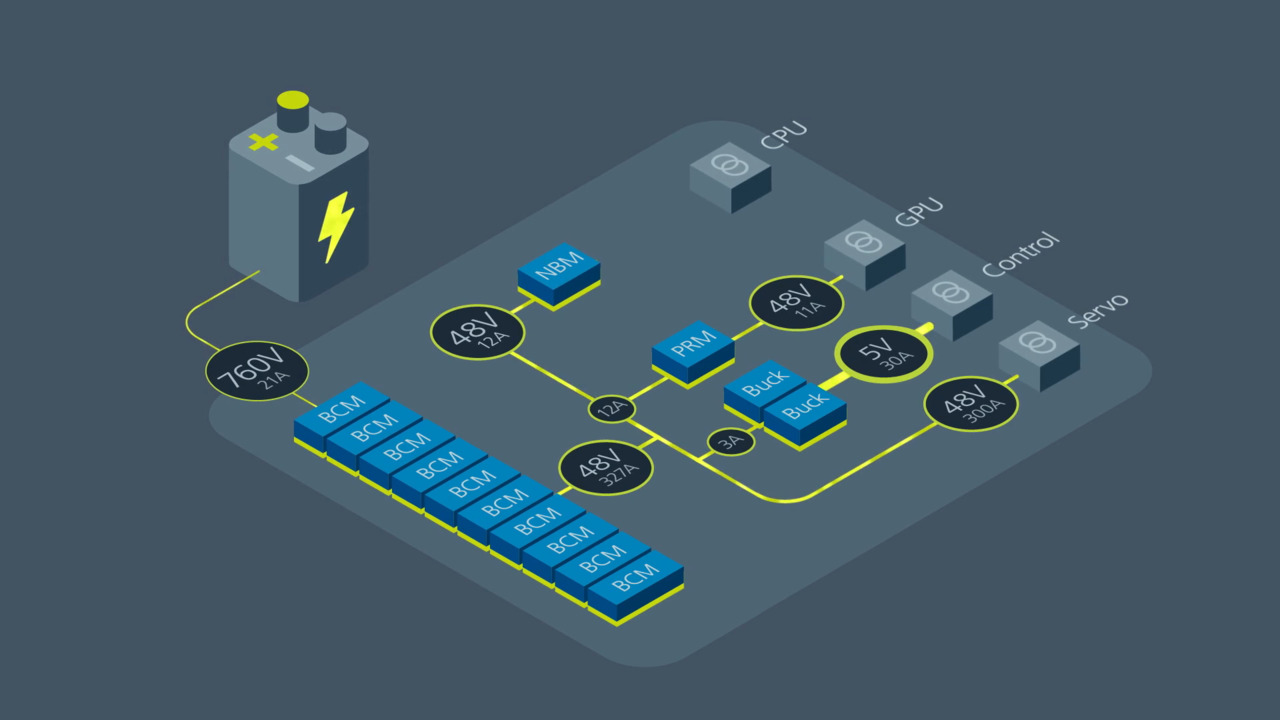
Modular PDN designs depend on the availability of a power module inventory that provides a wide range of power-related functions to enable flexible and scalable architectures (Figure 2).
") Figure 2: Modular PDN designs rely on a supplier with a wide variety of solutions to ensure flexibility and scalability. (Image source: Vicor)
Figure 2: Modular PDN designs rely on a supplier with a wide variety of solutions to ensure flexibility and scalability. (Image source: Vicor)
The basic zonal PDN architecture (upper left) distributes the 48 volt power source to local DC/DC modular converters, dropping the voltage to the required levels. If there is a change in the load requirements, a simple upgrade to a module with a higher power rating is made (upper center). Adding a new load simply requires the addition of another modular converter (upper right). There is no need to change the source configuration.
A reduction in power rail losses can be accomplished by a minor change to a factorized architecture (lower left). The factorized architecture splits the power regulation and voltage/current transformation into two separate modules. The pre-regulator module (PRM) manages the voltage regulation functions. The Factorized bus current is sensed to regulate the output voltage of the rail. The voltage transformation module (VTM), acting similarly to a DC transformer, manages voltage reduction/current multiplication. The VTM is smaller than a full DC/DC converter module and can be placed closer to the load to reduce resistance losses. Also, its low output impedance requires smaller output capacitors. This means that smaller ceramic capacitors can replace larger bulk capacitors near the load.
The need for greater power can be met by paralleling multiple converter modules (lower center). Updating to higher voltage sources, like 400 or 800 volts, can be accomplished by adding a fixed-ratio step-down module and a bus converter module (BCM) to reduce the source voltage down to safety extra-low voltage (SELV) bus levels (lower right). Note that the SELV bus is a safety standard that specifies the maximum voltage limit for electrical devices to ensure safety from electric shocks. SELV voltage levels are generally under 53 volts.
These examples provide a look into the flexibility and scalability that is available with the zonal architecture. Vicor offers a wide range of converter modules in its DCM series that fit these diverse applications. The company pioneered several revolutionary advances in power module design, including Converter housed in Package (ChiP) and Vicor Integrated Adapter (VIA) packages (Figure 3).
") Figure 3: Examples of the ChiP and VIA physical configurations of the DCM series. (Image source: Vicor)
Figure 3: Examples of the ChiP and VIA physical configurations of the DCM series. (Image source: Vicor)
These packages increase power density by a factor of four compared to earlier package configurations while achieving a 20% reduction in power losses. The ChiP uses magnetic structures mounted through a high-density substrate. Other components are mounted using a two-sided layout to double power density. Components are laid out symmetrically within the package for enhanced thermal performance. This advanced layout, along with optimized mold compound material, yields improved thermal paths. The ChiP module has low top and bottom surface thermal impedance. Cooling can be augmented using heatsinks thermally coupled to the top and bottom surfaces, as well as through the electrical connections. The VIA module adds integrated electromagnetic interference (EMI) filtering, better output voltage regulation, and a secondary control interface to the basic “brick” structural element.
Example DCM series DC/DC converter modules
The DCM series is an example of a regulated and isolated general-purpose DC/DC converter. Working from an unregulated wide voltage range source as an input, the converter generates a voltage-regulated power output at levels up to 1300 watts at output currents up to 46.43 amperes (A). It offers up to 4,242 volt DC isolation between input and output. Isolation refers to galvanic isolation, meaning that no current flows directly between the input and output. This isolation may be required by safety standards if the input voltages might be harmful to humans. Having the output floating relative to the input also allows for reversal or shift of the output polarity.
The DCM family uses a zero-voltage switching (ZVS) topology, which reduces the high turn-on losses common in conventional PWM converters by soft-switching the power devices. ZVS allows for operations at a higher frequency and at higher input voltages without sacrificing efficiency. These converters operate at switching frequencies randing from 500 kilohertz (kHz) to near 1 megahertz (MHz). Using this high switching frequency also reduces the size of the associated magnetic and capacitive energy storage components, improving power density. Power densities and efficiencies up to 1244 watts per cubic inch (W/in.3) and 96%, respectively, are achievable.
The DCM series is available in three package sizes: DCM2322, DCM3623, and DCM4623, with overlapping input voltage ranges and output power levels (Figure 4).
 Figure 4: Shown is a summary graph of the electrical characteristics of the DCM series DC/DC converters, including the input and output voltage ranges. (Image source: Vicor)
The input voltage ranges of the three families of converters cover 9 to 420 volts with SELV outputs in steps ranging from 3 to 52.8 volts DC. Output voltage limits can be trimmed over the range of -40% to +10% of nominal output voltage. The outputs have a fully operational current limit to keep the converter within its safe operating area, based on the maximum average power output, regardless of the output-voltage setting.
The DCM series includes fault protection for input undervoltage and/or overvoltage, over temperature, output overvoltage, output overcurrent, and output short circuit.
Examples of several DCM products, including all three package sizes and a range of input voltage and maximum power ranges, are shown in Table 1.
|
Table 1: The characteristics of commonly used DCM converters illustrate the range of input voltage, output voltage, and power levels available to meet a wide range of application requirements. (Table source: Art Pini)
The table summarizes the key characteristics of each of the example DCM converters and provides their physical dimensions. This is a small sample of the variety of DCM models available.
Typical applications
The DCM converters can be applied singly, and most can also be operated in parallel. When used alone, the output can feed multiple loads, including non-isolated point-of-load (POL) regulators (Figure 5).
") Figure 5: Shown is a typical application of the DCM3623T75H06A6T00 driving a direct load, as well as a non-isolated POL regulator. (Image source: Vicor)
Figure 5: Shown is a typical application of the DCM3623T75H06A6T00 driving a direct load, as well as a non-isolated POL regulator. (Image source: Vicor)
The circuit is straightforward. The components L1, C1, R4, C4, and Cy form the input EMI filter. The output capacitor COut-Ext, along with ROut-Ext, provides control-loop stability. The resistor can be the capacitor's effective series resistance (ESR), with a value of about 10 milliohms (mΩ). The capacitor must be located physically close to the converter's output pins. Rdm, Lb, L2, and C2 form a differential-mode output filter. The cutoff frequency of the filter is set to one-tenth the switching frequency.
Most DCM converters can operate with their outputs tied in parallel (array mode). This increases the power output delivered to the load by combining the outputs of up to eight modules (Figure 6).
") Figure 6: The circuit shows the parallel array operation of four DCM converters driving a common load. (Image source: Vicor)
Figure 6: The circuit shows the parallel array operation of four DCM converters driving a common load. (Image source: Vicor)
The external components perform the same functions as in the single converter example. In array mode, each DCM module must see a minimum value of output capacitance before any series inductance, and it must be located closer to the individual converter than to the output junction. In arrays where all “N” of the DCM modules are started simultaneously, the maximum value of the output capacitance may be up to N times Cout-Ext. There are also requirements for the power source impedance to be less than one-half the input impedance of the DCM array to assure stability and minimize ringing.
Conclusion
Applications such as vehicles and EVs are undergoing a notable shift from centralized to decentralized PDN architectures. The DC/DC converters necessary to meet the associated efficiency, power density, and weight requirements are challenging to design using discrete components. Instead, designers can reduce time and cost by using Vicor’s DCM series modular power supply solutions. As shown, these modules are at the forefront of advanced packages like ChiP and VIA, and innovative ZVS topologies are scalable and versatile, meeting a wide variety of diverse applications.
Disclaimer: The opinions, beliefs, and viewpoints expressed by the various authors and/or forum participants on this website do not necessarily reflect the opinions, beliefs, and viewpoints of DigiKey or official policies of DigiKey.