Connector Tutorial
Contributed By DigiKey
2017-09-05
Connectors may not be the most sophisticated part of a circuit, but they are certainly one of the most important parts. A circuit can be thought of in a couple different ways. The first way that most engineers may see a circuit is the theoretical side that can be represented on paper. While this is important, and certainly no circuit would work well without well thought out considerations, this is not the whole picture. Circuits are meant to go into a device or product that is meant to perform a certain function. Often these products can be very large like an airplane or a train which certainly could not be fit onto a large circuit board, they may have no circuit boards at all. For this reason, connectors are chosen to be quick and efficient ways to connect parts of circuits that are not necessarily on the same physical board, they are the bypass to the electron highway.
There are several different kinds of connectors in the marketplace, all of these serve the same purpose but do so in different ways. Some are meant to be used in automotive applications where vibration is an issue while others are meant to be outside in a static but weathered environment, the list never ends. Connectors help to cut down on manufacturing time, the time it takes a worker to solder several connections is much longer than the time it would take them to plug one connector into another. Hopefully this article can shed some light on connectors in general and which connector should be used for a given application.
Rectangular connectors
The term “rectangular connector” refers to the shape of the actual connector. It means that this connector housing will be rectangular in shape. These are often found on PCB boards because they are easy to use for manufacturing. A board will typically have either a through hole or surface-mounted male header that a female socket can fit onto, this is a good way to connect wires to a board. The female connector would have sockets with wires crimped onto them which would be connected to something else. An example of this would be the B2B-XH-A(LF)(SN), which is the male header, and the XHP-2, which is the female housing that would mate with the header. These products are from JST Sales America Inc. and will not work as-is. The XHP-2 is only a plastic housing, there are no sockets inside of this connector, so there are also no wires coming out of this connector. The sockets are proprietary accessories that are specific to the housing. While several contacts are very similar, it is always recommended to use the proper contacts that are made for the particular connector housing to ensure the connector will work. On the Digi-Key page for XHP-2 there is a section towards the bottom of the page that shows the sockets as an “Associated Product” (Figure 1).
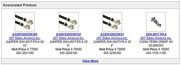
Figure 1: The “Associated Product” section for XHP-2 product page.
When manufacturers create a series of connectors, they often make the same style connector in many different positions. These will be labeled as a series of connectors like the XH Series that the first two examples came out of. Looking at the XH Series options in the Rectangular Connectors - Housings page, it is easy to see the associated products on all of the connectors have the same contacts offered for every housing. Typically most series of connectors will have a few different variations of contacts; there will be wire gauge options and sometimes different plating options. This is not a rule; some series have connectors with different size contacts, which is typical for connectors that have dedicated power pins and dedicated signal pins. An example of this can be seen with the AUHR-05V-H which is designed to have four signal pins and one power pin. Looking at the contacts one can see that there are two different styles, there is a power pin and a signal pin. The power pin is made for a larger 22-26 wire gauge while the signal pin is made for 28-30 gauge wire. Plating options refer to the finish on the contact. The most common plating options are tin and gold. Tin is cheaper and a suitable contact finish for many products that are not going to be in a corrosive environment or that do not need high reliability. Gold is better for applications in corrosive environments because gold is a noble metal that will not corrode. It is not recommended to mate a gold contact to a tin contact because flakes from both will intermingle and eventually allow for oxidization.
JST has made pre-crimped leads with 2” / 6” / 12” wires attached. An example of these leads would be the ASXHSXH22K152, which removes the need for an expensive hand tool for prototyping. Many manufacturers make pre-crimped leads for this purpose, there is an entire section devoted to this on the Digi-Key website called Jumper Wires, Pre-Crimped Leads. This can be helpful when developing a product with a low budget. If this was in a production run, then the tooling would ultimately be more economical than buying the pre-crimped leads. Just like finding the sockets for the housing, the Digi-Key website will have a tab listed for tooling on an individual contact page. For example, if looking at the SXH-001T-P0.6, the bare socket for the XHP-2, there will be a box for the tooling (Figure 2).
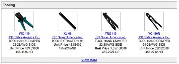
Figure 2: Tooling for the XH series connectors as shown on the product page.
Another tool that would be needed would be the insertion/extraction tool used for inserting the contacts and removing them. This is also listed in the “tooling” box, for this product it would be the XJ-06. Not all contacts will need an insertion tool but most will need an extraction tool if removing the contacts is desired. Ultimately, to use the male header B2B-XH-A(LF)(SN) mentioned earlier, the following would be needed:
- Male header – B2B-XH-A(LF)(SN)
- Female housing – XHP-2
- Either a socket like the SXH-001T-P0.6 which would need tooling like the WC-110 or a pre-crimped lead like the ASXHSXH22K152
- Insertion / Extraction tool for removing contacts - XJ-06
Rectangular connectors are very popular styles of connectors. They are not typically used for high current applications, but for small current applications they are great ways to power boards or send and receive signals economically. Most of these will have some form of a latch to keep them in place which is good for resisting vibration. These are not the only styles of rectangular connectors, there are rectangular connectors that are free hanging and panel mount as well. Take for example the 3-640441-2 from TE Connectivity AMP Connectors. While this connector can mate with a header on a board, it can also mate with the 3-647001-2, a free hanging connector. It is important to note that these connectors use a different form of termination than the previous connectors. The previous male was a through hole that would be soldered onto the board, and the previous female would use a crimp termination on the contact. These particular connectors use IDC (insulation displacement contact). This means there is a conductor that pierces the insulation to make contact with the wire.
There are several forms of contact terminations
- Crimp
- Solder
- IDC
- SCREW
Above are the four main kinds of terminations. Crimping involves having a contact and forming it around a wire to make electrical contact on the wire while holding the insulation with another part of the contact. TE Connectivity has put out a good video that illustrates what crimping is and what makes an acceptable crimp. The video is titled “Crimp Theory Fundamentals: Series I English”. Solder termination will either mean soldered onto a board for a through hole component, or there will be a cup or place on the connector to solder a wire onto. IDC or, insulation displacement contact, involves piercing the insulation to make contact, and screw termination means there is a screw that can clamp the wire down onto a contact. Solder termination would imply that the contact is already in the connector while a crimp termination would imply that the contacts come separately from the housings. On the Digi-Key website it can be confusing to know if a housing has contacts already or not. There are several pages of connector products on the Digi-Key web site; many of these pages have the word “Housings” in them. These pages will only be the housing and will usually have contacts listed as associated products. An example of this product page can be seen in Figure 3.
![]()
Figure 3: An example of a product page breadcrumb string for “Rectangular Connector – Housings”
When dealing with rectangular connectors, there is another point that needs to be brought up, the pitch of the pins. Pitch refers to the distance between the pins. The most common sizes are 1.27 mm, 2.00 mm, and 2.54 mm. These are by no means a standard; however, they are the most common. Typically in electronics, smaller is better, but this is a guideline not a rule. Board space will likely help to determine which pitch is going to work best for a given application.
Headers are very common connectors that are soldered onto a board and can have sockets easily placed on top of them. The first example was a header that was shrouded; there are also non-shrouded headers like the 61300311121 from Wurth Electronics Inc. (Figure 4).
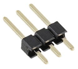
Figure 4: Wurth Electronics’ 61300311121 three position header.
These are very popular on evaluation boards where several aspects of a chip need to be tested. They can be used to easily take a board and put it onto a breadboard. An example of this would be the Arduino Pro Mini 3.3v. This board comes with circuitry to test and use the ATmega328 chip but there are no connections on any of the pins. It is possible to solder headers onto the board so the board can sit into a breadboard and be easier to use. Headers like this can use jumpers as well to short the pins together if needed. When choosing a jumper it is imperative to know the pitch of the headers. This particular header has a 2.54 mm pitch, so a jumper like the 382811-8 from TE Connectivity AMP Connectors would be acceptable because it also has the same pitch. Most breadboards will have a 2.54 mm pitch, this is often referred to as a 0.1” spacing for standard measurements. These will often mate to sockets that have the same face as a breadboard like the 5-534998-6.

Figure 5: The 5-534998-6 0.1 inch, twelve position socket from TE Connectivity.
That particular connector is meant to be soldered onto a board but there are also sockets that can be free hanging that attach to ribbon cable like the AWP 10-7240-T from ASSMANN WSW Components.
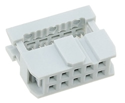
Figure 6: Assmann’s AWP 10-7240-T ten position, free hanging socket.
These types of connectors will usually use IDC termination to attach the ribbon cable and often have strain reliefs like the AWZ-10-T. Digi-Key sells cable assemblies for sockets like these that can be found in the Rectangular Cable Assemblies page. There are socket to socket options like the FFSD-05-D-04.00-01-N, socket to plug options like the FFMD-05-T-06.00-01-N, and plug to plug options like the FFMD-05-D-06.00-01 from Samtec Inc.
Circular connectors
Circular connectors are just like rectangular connectors in the fact that they connect parts of a circuit together. They are called circular connectors because they are circular in shape. These can be mounted on a board like the rectangular connectors, but will likely be seen more in a free hanging or panel-mounted situation. There are different ways to fasten circular connectors together, often a threaded connector or bayonet style connector will be used to assure the connector does not come unplugged. Many circular connectors are used in industrial and military applications. Often circular connectors can have high current capabilities and are easier to get an IP rating than a rectangular connector. An IP rating is an “ingress protection” rating which has to do with how well the connector can keep dust and water out. This is a very attractive quality when dealing with anything in a dirty or damp environment. Imagine a circuit that needed to provide power, ground, and a signal line to a sensor from a panel box to the top of a tower. This would be outdoors and exposed to rain and potentially snow as well. A good solution to this would be a panel mounted circular connector like the 17282-3SG-300 from Conxall/Switchcraft.
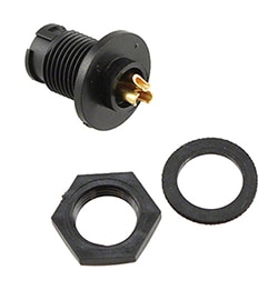
Figure 7: The 17282-3SG-300 three position circular connector from Conxall/Switchcraft has an IP67 rating.
This connector has an IP67 rating so it will work well submersed in up to a meter of water, making it the perfect solution for the potentially damp environment. A nice thing about circular connectors is that they are easy to mount on a panel due to their circular shape. Cutting a rectangular hole in steel or aluminum is much more difficult than cutting a circular hole. The 17282-3SG-300 has a cover that can be used when it is not in service (16295) and a small gasket that can be used to help keep water out (16293). This connector can mate with a free hanging connector like the 16282-3PG-311. These are fastened with a bayonet lock so they can be easily mated and unmated. This connector may not be the solution to all outdoor problems, but it clearly illustrates some of the positive attributes of circular connectors.
Like rectangular connectors, circular connectors can often have accessories and tooling. The Digi-Key website will usually have all of the accessories listed on a particular product page and tooling can usually be found when looking at the actual contacts for a connector. As mentioned before, the page on the Digi-Key website that says “Housings” will not have contacts while the page that simply says “Circular Connectors” will have contacts in them already. Many circular connectors fall into the category of mil-spec connectors. These connectors are standardized so that regardless of who the manufacturer is, the parts all meet the same specifications. In addition to the mil-spec connectors, there are derivative series that follow the same guidelines but do not go through the certifications that the real mil-spec connectors go through. The derivative series will be exactly the same as their mil-spec counterparts; they will simply not have paperwork showing that they are mil-spec parts. These derivative counterparts will follow their mil-spec counterparts numbering schemes very closely. Often these numbers will only involve a prefix change on the part number.
To examine these numbering schemes, take the example of the MS3102E14S-2P. The same part can be seen from two different manufacturers, ITT Cannon and Amphenol Industrial Operations. The number actually calls out all the attributes of the connector and since the numbers are standardized, the connectors with this exact number will be interchangeable from different manufacturers. To further investigate, this number will need to be broken down into sections by using the “how to order” section on page 70 from the Amphenol series datasheet.
MS – This designates Military Standard
3102 – This calls out a box mounting receptacle with an environmental resisting service class
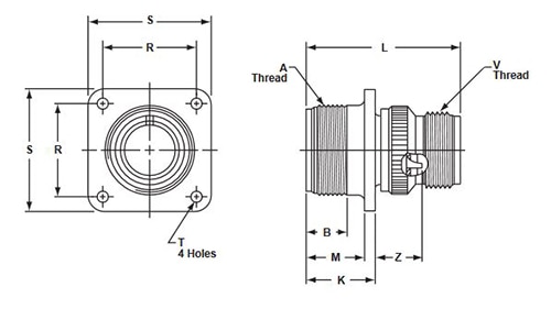
Figure 8: Representational drawing of Amphenol circular connectors with dimensional designations. (Image courtesy of Amphenol Industrial Operations)
14S – (On its own) this calls out the shell size of the connector

Figure 9: Dimensional numbers for a shell size designation of 14S. (Image courtesy of Amphenol Industrial Operations)
14S-2 – This calls out the contact arrangement

Figure 10: Contact arrangement for the 14S shell size. (Image courtesy of Amphenol Industrial Operations)
P – Calls out a pin contact
The number details what the attributes of the connector are. The box mounting receptacles will all look like Figure 8; however, there are different dimensions for different shell sizes. The contact arrangement describes how the contacts will be laid, as depicted in Figure 11 for the MS3102E14S-2P.
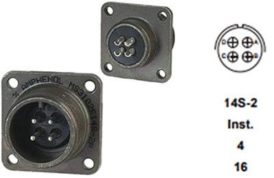
Figure 11: Amphenol’s MS3102E14S-2P contact arrangement for the 14S-2 designation. (Image courtesy of Amphenol Industrial Operations)
This particular connector comes with the contacts loaded into it; however, many of these will have crimp contacts. To find which contacts are orderable for these, it is imperative to know what the contact size is. The contact size will be called out under the contact arrangement. An example can be taken from one of the MIL-5015 derivative parts 97-4102A-18-4S. This part replaces the MS with a 97 because that connector belongs to the 97 series. The 4102A is still another box receptacle like the previous MS3102E14S-2P which can be seen from the 97 series catalog:

Figure 12: Representational drawing of Amphenol’s 97-4102A box receptacle with dimensional designations. (Image courtesy of Amphenol Industrial Operations)
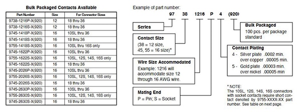
The 97-4102A-18-4S will have an 18-4 contact arrangement which calls out four #16 contacts. Page 26 of the catalog has ordering information for the contacts. Figure 13 is an image of the bulk packaged contacts ordering information.
Figure 13: Bulk packaged contacts ordering information. (Image courtesy of Amphenol Industrial Operations)
Using the previous information about this connector will help in finding the proper contact. It calls out #16 contacts and the shell size of this particular connector is 18-4. Using this information, the contact can be derived by looking at the eighth row on the table. This calls out size 16 and for connector sizes 18 to 36, the resulting socket contact part number of 9745-1622S-X(920) is determined. For the purpose of ordering this through a distributor like Digi-Key, it is good to point out that some of the nuances of the part number can be lost. An example of this is can be seen with the contact that was listed. While the Amphenol ordering guide says the part number is 9745-1622S-X(920), the manufacturer’s part number on the Digi-Key website says 97-45-1622S-4(920). The X before the (920) is a generic placeholder for another option of silver plating or gold plating. The 4 on the Digi-Key website calls out that this has silver plating. There is even another name for this connector under “other names” on the product page on the Digi-Key website: 97451622S40920. If this causes confusion, which it undoubtedly can, it is good to mention that distributors like Digi-Key have a team of people who can help in understanding how to order the correct connectors. To contact Digi-Key simply call 1-800-344-4539 and ask to speak with an applications engineer.
DIN connectors are another example of circular connectors. These are small circular connectors that would usually be used for signal-level communications. These will have a 13.2 mm diameter across the face of the connector. This can be illustrated with the SD-80 from CUI Devices which has a 13.2 mm diameter across the face. DIN connectors will all have the same size of face; however, there are several contact arrangements that can be selected depending upon the arrangement that is needed. There will always be a notch as well that allows the connector to only be mated one way. Figure 14 is a clip from the SD series datasheet that illustrates this point.
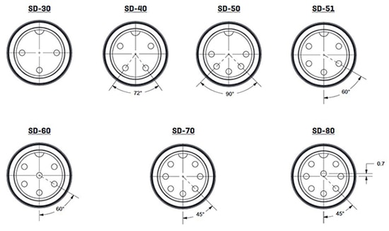
Figure 14: CUI Devices’ SD series DIN connector contact arrangements. (Image courtesy of CUI Devices)
These connectors will also have another rating for how many times they can be mated and unmated. On the datasheet it will be called out as “Life” and it stands for how many times these can be reliably mated an unmated, this is often referred to as “Mating Cycles”. This particular model will have 5,000 cycles before the end of its life. This can be found under the “Specifications” part of the datasheet (Figure 15).
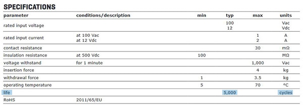
Figure 15: Specifications for CUI Devices’ SD series DIN connectors with the “life” or mating cycles highlighted. (Image courtesy of CUI Devices)
Terminal blocks
Terminal blocks are used to connect two or more wires together. Often there will be a screw lock to hold the wire down inside of the terminal block. These are typically plastic insulators with contacts on them where each circuit is separated by an insulator. There are many different kinds of terminal blocks, from headers, plugs, receptacles, barrier blocks, wire to board, DIN rail channel, interface modules, and panel mounted options, all of which can be found on the terminal block portion of the Digi-Key website. These will usually have either a screw termination, or a spring termination.
Barrier blocks
Barrier blocks will be plastic housings with screw terminals for the wire termination. An example of one of these would be the TB100-08SP from Eaton (Figure 16).

Figure 16: Eight circuit barrier block (TB100-08SP) from Eaton.
These are used to connect wires on either side of the block together. This particular model can handle up to 30 amps per contact with up to 300 V. Many barrier blocks have jumpers that are made to connect one circuit to another on the block itself. These should be called out in the documentation from the manufacturer. The TB100-08SP belongs to the Magnum TB100 series. On the first page, this product can be found under the “Dimensions – in” table in the 08 poles row (Figure 17).
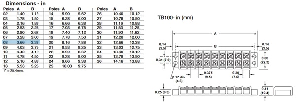
Figure 17: Eaton’s Magnum TB100 series dimension specifications. (Image courtesy of Eaton)
To find the associated hardware look on the second page of the datasheet. There are a few different options for screws, quick connects, and jumpers listed. Often manufacturers will have all of these accessories listed right on their datasheet. For this particular product there are three jumpers listed (Figure 18).

Figure 18: Jumpers for the TB100 series terminal blocks. (Image courtesy of Eaton)
These have very short part numbers and are difficult to find as a result. They will often not be listed on the same page for a distributor website. These would fall into the Terminal Blocks – Accessories – Jumpers page on the Digi-Key website. To easily see if this item is available, rather than putting the number into the entire website search bar, it will be more efficient to find the terminal block accessory page and put this into the search within results tab like the Figure 19 search for the J101.
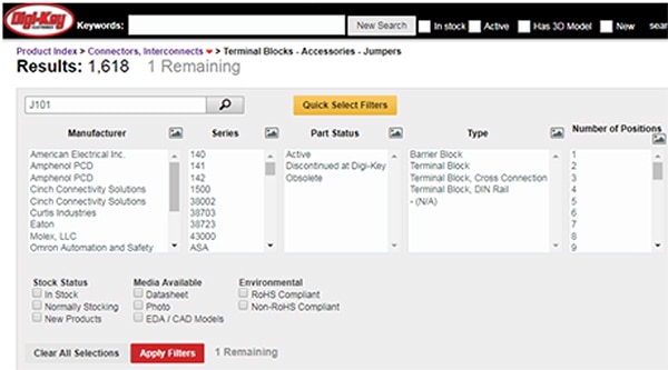
Figure 19: Digi-Key part search example for the J101 jumper.
The result that will be found when doing this will be the J101/J. This will be the correct jumper for the TB100 series that TB100-08SP belongs to; it has the proper pitch of 9.53 mm and is shaped like the image on the datasheet. When regarding accessories, the Digi-Key website will usually have a “For Use With/Related Products” entry in the “Products Attributes” table to show which series or part an accessory goes with (Figure 20).
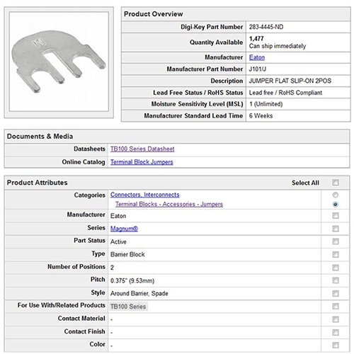
Figure 20: Digi-Key part search page for the J101/J jumper highlighting the “For Use With/Related Products” product attribute.
Headers, plugs and sockets
These are very much like the headers and free hanging sockets mentioned in the rectangular connector portion of this article. The header will often be mounted onto a board and the free hanging end will fit into the header receptacle. An example of this is the OSTOQ063250 from On-Shore Technology, Inc. which mates to the OSTTJ0631530. Often times these can be interchangeable from manufacturer to manufacturer. If looking at the OSTJ0631530 on the Digi-Key website, to find similar products that can mate with this, start by selecting the pitch, number of positions, and type from the product specifications (Figure 21).

Figure 21: When searching for a mating connector on the Digi-Key website, check the appropriate boxes.
From there hit the “Search” button at the bottom of the page (Figure 22).

Figure 22: After all matching attributes are selected, click the search box at the bottom of the page.
Figures 23, 24, and 25 show the face of several of the resulting connectors.

Figure 23: 1827745 – Phoenix Contact.

Figure 24: TJ0631530000G – Amphenol Anytek.

Figure 25: 1792810000 - Weidmuller.
The front of each of these manufacturers’ parts are keyed the same. This will be true for many of the pluggable terminal blocks which make them more convenient to work with. Each pitch will have a slightly different face. These plugs are all free hanging with sockets for contacts, there are also free hanging receptacles with male pins. An example of this would be the 1858073 from Phoenix Contact. Alternatively, there are receptacles with male pins that can be mounted to something but still retain a screw termination rather than a solder termination like the 1788570 from Phoenix Contact.
So far all of these have had screw terminations, but spring termination is also quite popular. An example of a spring termination is the 1881367 from Phoenix Contact. This connector uses springs on the back to hold the wire in place; by depressing the spring it is possible to remove the wire (Figure 26).

Figure 26: 1881367 – Phoenix Contact.
DIN Rail terminal block
DIN rails are popular in many industrial applications, and there are terminal blocks created for DIN rail applications. These will function to connect circuits like the previous examples, but will be quite aesthetically different. They will all have a slot on the bottom of them for attaching to a DIN rail like the 1020000000 from Weidmuller (Figure 27).
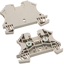
Figure 27: Weidmuller’s 1020000000 DIN rail terminal block.
These types of terminal blocks will usually have a plate that can be added to enclose the internal chamber of the terminal block. These can be found on the associated tab on the Digi-Key website, an example would be the 1050000000 which is the endplate for the 1020000000. There are also jumpers if it is necessary to connect one of these terminal blocks to another like the 1693800000.
Interface modules
Interface modules can be thought of as an adapter. They will have a control side connection and a process side connection. An example would be the DSUB-9-MF from American Electrical, Inc. This connector allows for either a male or female 9 position D-Sub connector to be easily broken out into discrete wires as seen in Figure 28.

Figure 28: The DSUB-9-MF interface module from American Electrical, Inc.
There are many other forms of interface modules. Another great example of an interface module is an RJ45 Jack going to discrete wires like the 2900701 from Phoenix Contact (Figure 29).
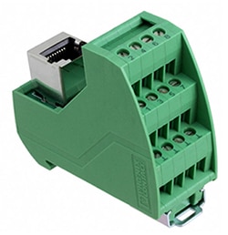
Figure 29: Phoenix Contact’s 2900701 interface module.
Panel mount
Terminal blocks can be panel mounted as well. The mating side will follow the same rules that the free hanging and mounted terminal blocks follow. Basically, if the pitch of the connector is known, it will likely mate to another manufacturers terminal block. An example that could double as a wall outlet for power would be the 1861167 from Phoenix Contact. There will usually be mounting holes on either side of the connector as shown in Figure 30.
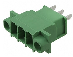
Figure 30: Panel-mount terminal blocks usually feature mounting holes as seen in Phoenix Contact’s 1861167.
It is important to note that this will not come with screws. Often hardware is separate, and this is no exception. Like previously stated, there will usually be an associated section on the Digi-Key website that will show accessories for these. This particular model has a hardware set that is sold with it, 0728263.
D-Sub
D-Sub, otherwise known as D-subminiature, connectors get their name by the shape of their mating side; they are shaped like a D. There are standard shell sizes for D-Sub connectors that will have a standard pin number. On the Digi-Key website there will be a shell size and a connector layout designator that will help to identify this. This can be illustrated using the 171 series from NorComp Inc.
There are five shell size options and connector layouts, each of which correlates to a number of pins.
|
Table 1: A selection of standard D-Sub shell size and connector layouts.
Like the standard shell sizes and layouts, there are also high density layouts which have the same shell size but an extra row of contacts fitting a higher density of contacts into the same area. A good illustration of this is the AMPLITIMITE HD-22 series from TE Connectivity AMP Connectors
|
Table 2: A selection of high density D-Sub shell size and connector layouts.
These are not all of the shell sizes or layouts by any means, but this brings up most of the major ones. Many D-Sub connectors have power pins and coaxial pins as well. An example of this is the DCMM-13W6S from ITT Cannon. This connector has seven signal pins and six pins that can be used for either coax or power. This still has the 4(DC,C) size face as the previous examples but a different layout than both of the previous 4(DC,C) connectors.
Barrel connectors
Barrel connectors are often used to supply power to consumer grade electronics. They are round in shape and come in many different sizes. These can be found on all kinds of electronic devices such as wall adapters for laptops. An example of a barrel connector would be the PP3-002A from CUI Devices which is a fairly standard size (Figure 31).
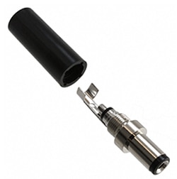
Figure 31: CUI Devices’ PP3-002A barrel connector.
This has an outer diameter of 5.5 mm and an inner diameter of 2.1 mm which is a very popular size of barrel connector. Most barrel connectors have either a 2.1 mm inner diameter or a 2.5 mm inner diameter and typically they will have a 5.5 mm outer diameter. There are many different sizes for these connectors, so assuming a 2.1 mm or 2.5 mm diameter can cause problems. The absolute best way of knowing the size of a connector is having the documentation to it, the manufacturer should have documented the physical dimensions at some point. If there is no documentation available, then it is recommended to use a caliper to determine the diameter of the plug. These types of barrel plugs will mate with barrel jacks like the PJ-036AH-SMT-TR shown in Figure 32.
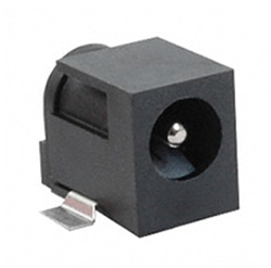
Figure 32: The PJ-036AH-SMT-TR barrel jack from CUI Devices.
There are also barrel audio connectors as well. One of the most recognizable ones would be a 1/8” plug like the SP-3501 from CUI Devices. This is a very common headphone plug that can be used on many 1/8” jacks like those found on computers, cell phones, many MP3 players, and other devices that play audio.

Figure 33: Standard 1/8” audio jack (CUI Devices’ SP-3501 shown here).
The vernacular many distributors like Digi-Key will use to describe such a connector will be a 3.5 mm plug. The reason many distributors call them this is because they have an actual 3.5 mm diameter which is 0.138”. This dimension can be taken off of the drawing for this product (Figure 34).

Figure 34: Dimensions for a 3.5 mm audio plug.
One of the very nice things about this particular style of connector is that it will not matter which manufacturer the connector comes from. The 1/8” jack is an industry recognized size for a connector. The SP-3501 would work on any consumer grade 1/8” jack regardless of the manufacturer. It is still important to note that not all connectors that look like this will be this size, 1/8” and 1/4” are very standard. 1/8” connectors will be used for plugging in headphones or small computer speakers. Typically, 1/4” connectors used to be used on phone lines and are now more commonly used to connect electric guitars through their pedals and into their amp. Those two sizes are standard and easy to cross from one manufacturer to another. Other barrel audio connectors may not work the same way. An example can be taken from the SP-25401 from CUI Devices (Figure 35).
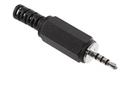
Figure 35: CUI Devices’ SP-25401 is a 2.5 mm jack.
This connector looks very similar to the SP-3501; however, its diameter is a full millimeter smaller than the SP-3501. This has a 2.5 mm diameter and would not mate with the jack for the SP-3501. It is important to know what the diameter is of these to avoid unsuccessful mating, but once the diameter is known, it is easy to mate that to another manufacturer’s part that has the same size. The SP-25401 also is different from the SP-3501 in the fact that it has four conductors instead of three. This can be seen by looking at the metal conductor on the plug, there are three insulators on the SP-25401 making four conductors. The SP-3501 has two insulators making three conductors which would be typical of an audio plug meant for stereo sound.
USB
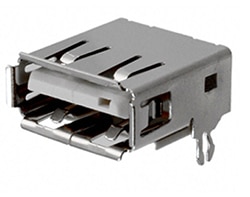
There are several different forms of USB. One of the most popular types of USB is USB A which is often used for peripheral devices on computers, or for charging many appliances. Usually the computer will have a female USB A and the device side will be a male. These will often have four contacts, two for power and ground and two for data. An example of one of these connectors would be the 87583-3010RPALF from Amphenol FCI (Figure 36).
Figure 36: Amphenol’s 87583-3010RPALF USB A receptacle.
This connector will have four contacts on it along with a retention post for holding it down onto a PCB board. When using a connector like this it is imperative to know how to lay out the PCB board. Thankfully, manufacturers typically leave a recommended footprint for these components as illustrated in Figure 37 for the 87583-3010RPALF.

Figure 37: The recommended PCB layout for the 87583-3010RPALF USB A receptacle.
These connectors will follow a standard, so it is possible to mate one manufacturer’s part with another. If an engineer was using the 87583-3010RPALF for their female side, it would be acceptable to use the 048037220 from Molex LLC to mate with it (Figure 38).
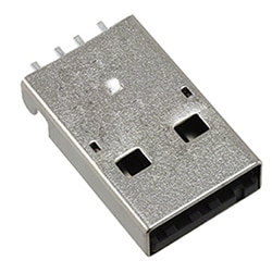
Figure 38: A USB A male plug, the 0480372200 from Molex.
The standardization and interchangeability between manufacturers makes USB a very popular choice in today’s marketplace. USB A is not the only USB connector on the market; there are several other types such as USB B which is very popular as well. USB B connectors are found on many printers and Arduino Uno’s. They are a little more robust than the USB A type and have their contacts laid out differently. USB A has all of the contacts in a line while USB B has its contacts split with two above the insulator and two below the insulator like the USB-B1HSW6 from On-Shore Technology, Inc. Figure 39 illustrates this difference, USB A is pictured on the left and USB B on the right.
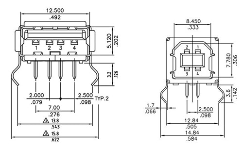
Figure 39: The different contact layouts of USB A (left) and USB B (right).
Since the female side has the four contacts separated into two rows by the insulator, the male side of USB B will have the four contacts separated with two on top and two on the bottom like the A-USBPB-N from ASSMANN WSW Components. Figure 40 shows how the contacts are laid out on this component, this will be standard for all USB B connectors.
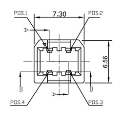
Figure 40: The pin layout of the ASSMANN A-USBPB-N socket.
The USB-mini is also a popular style of USB connector. These were used on many older cell phones and peripheral devices. An example of this would be the UX60A-MB-5ST from Hirose Electrical Co. LTD (Figure 41).
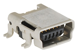
Figure 41: Hirose’s UX60A-MB-5ST USB-mini receptacle.
These are smaller than the USB A and USB B. The mating connectors for these will be free hanging like the UX40A-MB-5P which by itself isn’t as identifiable, but when attached to a cable quite recognizable. Figure 42 shows the UX40A-MB-5P on the left and the UX40-MB-5PP-500-1002 on the right which is the cabled version of the UX40A-MB-5P.
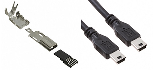
Figure 42: Hirose’s UX40A-MB-5P USB-mini (left) and the cabled version, the UX40-MB-5PP-500-1002 (right).
Something to point out would be the difference in pin count between the USB A and USB mini. The USB A has four pins, one for power, one for ground, and two for data. The USB mini has five pins, these will be for the same functions as the USB A, but also there is a fifth pin referred to as the sense pin. The fifth pin allows the cable to send a signal to let the device communicate whether it needs to be a master or a slave. When there is a USB cable that has USB A and USB mini, the sense pin will be shorted to ground. This is called USB On The Go, or USB OTG. Maxim Integrated has an article that goes further into depth regarding this titled USB On-the-Go Basics.
Coaxial connectors
Coaxial connectors are used to terminate coaxial cable. To understand the connector it is important to first understand what coaxial cable is. It is a solid conductor which is surrounded by a dielectric material which will be covered by a second conductor. Connectors for these are laid out in exactly the same manner. These connectors will have a center conductor, an insulator, and a second conductor surrounding the inner conductor like the 1909763-1 from TE Connectivity AMP Connectors (Figure 43).
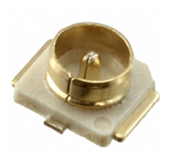
Figure 43: The 1909763-1 coaxial connector from TE Connectivity.
As illustrated, the center male pin does not touch the outside shell of the connector. This particular connector is an Ultra Miniature Coaxial Connector. There are many different kinds of coaxial connectors in the market. Some of the major ones are BNC, SMA, RP-SMA, UMCC, along with several others. There are several things that need to be considered when choosing a coaxial connector. The style of connector must be the same; it is not possible to mate a BNC connector to an SMA connector without an adapter. Once the style has been determined the next step is knowing the impedance. Some styles have several different impedance options, a BNC connector would be an example of this. When looking at BNC connectors at the Digi-Key website it will be evident that there are a couple of impedance options, 75 Ω or 50 Ω. It is recommended to match the impedance to that of the mating connector. If the mating BNC connector is 75 Ω then it will be imperative to choose a 75 Ω connector. If an engineer was tasked with terminating a coaxial cable onto an SMA connector, they could follow the following line of thinking. An SMA connector has 50 Ω impedance and will mate to another SMA connector. If the connector that was already in place was a panel mounted receptacle with a female socket like the 132139 from Amphenol RF Division, the engineer knows he needs a free hanging plug with a male pin like the 132114 from Amphenol RF Division. If one side is a receptacle with a socket, the other side will need to be a plug with a pin. Looking at the 132114 on the Digi-Key website there will be an entry in the “Product Attributes” box that says “Cable Group”. This will show the applicable cable that this connector can use (Figure 44).
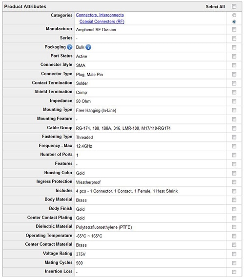
Figure 44: The entry in Digi-Key part search for the 132114 part shows the cable group applicable for this connector.
Once the cable group has been found, it will be time to locate one of these cables. If there is a large project that will involve several hundred, it may be better to go to the part of the website that has RF cables which can be found in the Cables, Wires > Coaxial Cables (RF) page on the Digi-Key website under the “Cables, Wires” page and pick one of the cable groups from the “Cable Group” option on the parametric search (Figure 45).
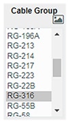
Figure 45: Select the desired cable group option to find the appropriate parts.
One of the options on the cable group for the 132114 was RG-316 which would leave the 9316 BR005 from Alpha Wire as an option for a cable. If there were only a few cables that were needed, it may be more economical to look through the coaxial cable assemblies on the Digi-Key website which can be found on the Cable Assemblies > Coaxial Cables (RF) page. From that page it would possible to select an SMA to SMA connector and then select the RG-316 cable type. The 135101-01-06.00 from Amphenol RF Division is a good example of a cable assembly that would work well if only 6” of cable is needed (Figure 46).
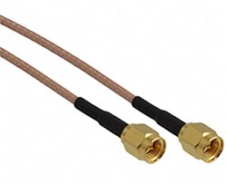
Figure 46: The 135101-01-06.00 SMA, 6” cable assembly from Amphenol.
This cable assembly has the RG-316 cable connecting two SMA plugs with male pins that are free hanging. Often there will be cable assemblies for connectors. The reason for this is because cable is expensive because it is usually sold in large quantities and often small cable runs are all that is necessary. Manufacturers know that tooling is expensive so they often have assemblies that they put together that can meet certain needs for their customers. When looking at coaxial connectors, these cable assemblies will often be much cheaper than the cost to create a cable assembly.
Summary
There is much more that can be said about connectors. Hopefully this article has shed some light on different styles and types of connectors. This is an absolutely huge topic that is difficult to summarize in a few short pages. Some of the ideas covered here were the different types of connectors, what they could be used for, and what goes into choosing these connectors. Often connectors will come assembled; however, sometimes there will just be a housing with the wires and contacts required to be added afterwards. There are several different ways to terminate a connector such as soldering, crimping, using an insulation displacement contact, or screw termination. There is much more that could have been written regarding connectors, but hopefully this is a good start to understanding the vast variety of connectors and how they can be used to help complete a circuit. Connectors can often be overlooked when designing a circuit and when in reality, even though they are simple parts, they can make or break a circuit.
All of these connectors and many more can be found on the “Connectors, Interconnects” page on the Digi-Key website.

Disclaimer: The opinions, beliefs, and viewpoints expressed by the various authors and/or forum participants on this website do not necessarily reflect the opinions, beliefs, and viewpoints of DigiKey or official policies of DigiKey.


