Configurable 4-in-1 Regulator Powers FPGAs, ASICs and Microprocessors
Contributed By Electronic Products
2014-09-09
Whether the end use is in telecom equipment, datacenter servers, or other applications, system boards today are populated with FPGAs, ASICs, microprocessors, memory, and other parts that enable it to handle numerous tasks. In a distributed architecture, each of these devices is normally driven by a dedicated and efficient point-of-load (POL) regulator or buck DC/DC converter. As a result, it is common to see several POL regulators spread across such boards. To consolidate these POLs into a single package, Linear Technology has released a step-down µModule regulator that can be configured to regulate four independently adjustable outputs using just a few external passive components.
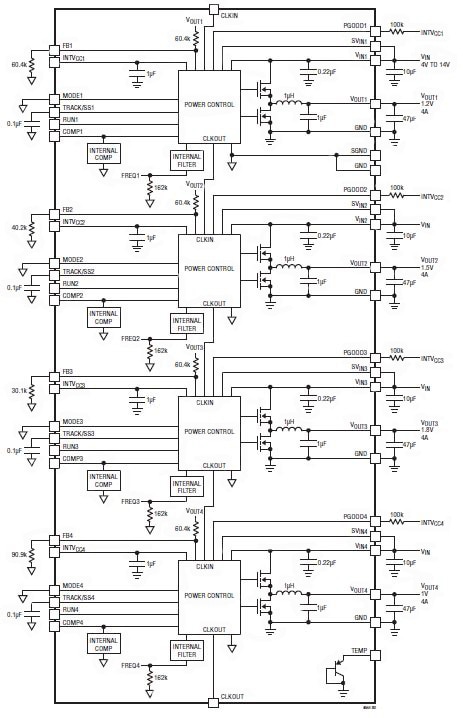
Featuring housing power switches, DC/DC controller, inductors, and compensation components inside a single BGA package, Linear’s LTM4644 regulator can be tailored to deliver single-, dual-, triple-, or quad-output using a handful of external passives. There are four independent regulators inside the BGA, each capable of delivering up to 4 A continuous output current using few external input and output capacitors and resistors. Each independent regulator provides precisely-regulated output voltage that is programmable from 0.6 to 5.5 VDC via a single external resistor over a 4 to 14 VDC input voltage range (Figure 1). With an external-bias voltage, this module can operate from an input voltage as low as 2.375 VDC.
Because each regulator of the µModule employs current-mode control with internal feedback loop compensation, the regulators can be paralleled with accurate current sharing. Consequently, the four regulators form an array with 4 A per output. As illustrated in Table 1, the array can be configured to deliver a single output voltage, dual outputs, triple outputs, or quad outputs. Since four regulators are paralleled in a single output configuration, it is capable of delivering 16 A of output current with a voltage range of 0.6 to 5.5 VDC. Likewise, in dual-output configuration, three regulators can be paralleled to deliver 12 A from one output, 4 A from the other one, or two can be paralleled for each output to deliver 8 A per output. In triple-output configuration, two units are paralleled to provide 8 A from one output and 4 A each from the two other outputs. Output overvoltage and overcurrent fault protection are included in these regulators.

Figure 1: LTM4644 incorporates four independent regulators inside a single BGA package with each of them capable of delivering up to 4 A continuous output current using few external input and output capacitors.

Table 1: The four independent outputs of LTM4644 form an array with 4 A per output. The array can be configured to provide a single output, dual outputs, triple outputs, or quad outputs.
The default operating frequency is internally set to 1 MHz. In most applications, no additional frequency adjustment is required. However, if the switching frequency for the desired application must be other than 1 MHz, the μModule regulator can be externally synchronized to a clock from 700 kHz to 1.3 MHz.
Besides offering the flexibility of configuring multiple regulated output voltages at a variety of current levels, LTM4644 also offers separate input pins that allow users to power the four channels from different input rails or a common supply rail with a voltage range of 4 to 14 VDC.
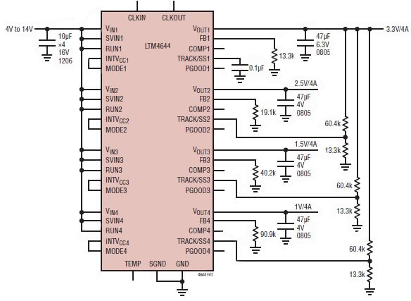
A typical application circuit with four regulated outputs is shown in Figure 2. In this circuit, external component selection is primarily determined by the input voltage, the output voltage, and the maximum load current. A table in the product datasheet gives specific external capacitor requirements for specific output voltages. For certain specific capacitor values, it also gives part numbers with supplier names.

Figure 2: A typical application circuit for LTM4644 with four regulated outputs.
However, per the product datasheet, there are restrictions in the maximum step-down ratio that can be achieved for a given input voltage due to the minimum off-time and minimum on-time limits of each regulator. The minimum off-time limit imposes a maximum duty cycle which can be calculated as:
Where tOFF(MIN) is the minimum off-time (70 ns typ for LTM4644) and fSW is the switching frequency. Conversely, the minimum on-time limit imposes a minimum duty cycle of the converter, which can be calculated as:
The above is where tON(MIN) the minimum on-time (40 ns typical for LTM4644). According to the manufacturer, for each regulator channel a 10 µF input ceramic capacitor is recommended for RMS ripple current decoupling. With an optimized high-frequency, high-bandwidth design, only a single low ESR output ceramic capacitor is required for each regulator channel to achieve low-output-voltage ripple and very good transient response. Additional output filtering may be required by the system designer if further reduction of output ripple or dynamic transient spike is required.
Output voltage tracking can also be programmed externally using the TRACK/SS pin of each regulator channel. The outputs can also be tracked up and down with another regulator. Figure 3 shows a schematic of ratiometric tracking where the slave regulator’s (VOUT2, VOUT3, and VOUT4) output slew rate is proportional to the master’s (VOUT1). Other features offered by the quad regulator include guaranteed ±1.5 percent DC output voltage accuracy from ─40ºC to 125ºC temperature range. What’s more, it offers an internal temperature sensing diode and is protected from overvoltage, overtemperature, and short-circuit conditions.

Figure 3: Schematic for ratiometric tracking of four channels of the quad μModule regulator.
In summary, using a handful of external capacitors and resistors, a single compact μModule regulator can be easily configured to provide multiple outputs for a variety of voltage and load current requirements for the myriad semiconductor devices found on the printed circuit boards of communications, data storage, industrial, transportation, and medical systems.
For more information on the product discussed in this article, use the link provided to access product pages on the DigiKey website.
Disclaimer: The opinions, beliefs, and viewpoints expressed by the various authors and/or forum participants on this website do not necessarily reflect the opinions, beliefs, and viewpoints of DigiKey or official policies of DigiKey.


