Component Designs to Satisfy Functional Safety Standards
Contributed By DigiKey's North American Editors
2022-12-15
Safety is a top priority in industrial applications to protect employees and equipment from injury and damage. Welding, cutting, and pressing operations as well as high-speed axes and those handling dangerous workpieces or substances pose the most threat. In the U.S., plant operators must satisfy Occupational Safety and Health Administration (OSHA) regulations with safe equipment, operational procedures, and training protocols. Complementing these systems should be plant-specific analyses to identify pragmatic ways to enhance worker well-being and equipment longevity. In addition, automated machinery must satisfy functional safety requirements via automatic machine actions or corrections to potentially or certainly unsafe conditions or failures.
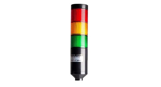 Figure 1: Light towers today use LEDs for efficiency and visibility. Some enhance safety with built-in buzzers to emit a siren to 100 dB during safety breaches. (Image source: Menics)
Functional safety systems include electronics in the form of sensors, I/O, controls, switches, electromechanical components, fluid-power components, and software that detect dangerous conditions and change the machine state to prevent dangerous situations from arising. First originating in the European Union, today functional-safety design and regulations apply to suppliers, machine builders, and end users around the world. The harmonized European Norm (EN) and International Electrotechnical Commission (IEC) EN/IEC 62061 standard — listed in EU Machinery Directive 2006/42/EC — and the International Organization for Standardization (ISO) EN/ISO 13849-1 standard are the most applied.
ISO 13849-1 and IEC 62061 can be cross-referenced, and OEMs and end users are free to use either. The only caveat is that functional safety relates to machines and controls and not devices or components … though the latter may offer functionalities supporting the satisfaction of a given safety rating.
EN/IEC 62061 details requirements and recommendations as safety integrity levels for the design, integration, and validation of permanently installed (nonportable) machine or plant-installation SRECS — consisting of safety-related electrical, electronic, and programmable controls. EN/IEC 62061 safety integrity levels (SILs) grade a system’s functional safety from 1 (most rudimentary) to 4 (most integrated and sophisticated) with SIL3 the highest possible for machines. Risks dictating the required SIL include the regularity of risk exposure, severity of the potential injury, incidence probability, and likelihood that a machine operator’s evasive maneuvers can help avoid harm.
|
Table 1: Required SIL levels depend on the severity of injury should a given unsafe condition occur as well as the likelihood of that condition occurring. (Table source: IEC)
In contrast, EN/ISO 13849-1:2005 details requirements and recommendations based on SRP/CSs — safety-related parts of control systems. SRP/CS performance levels allow for quantification of machine safety capabilities no matter the subcomponents. The standard employs well-known performance level (PL) ratings of functional safety — ranging from “a” (most rudimentary) to “e” (most integrated and sophisticated). Risks dictating the required PL include those applicable to SILs as well as the frequencies and durations of repeated exposures to the machine hazard. In addition, a complete PL rating includes a Category number (to indicate the overall system architecture) and the mean time to dangerous failure or MTTFd.
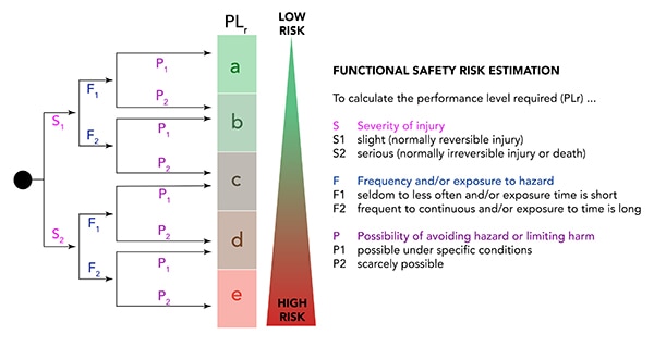 Figure 2: The appropriate functional safety level for a given installation depends on qualitative variables, quantitative values, and the results of software-based analysis. (Image source: Design World)
IEC 61508 and IEC 62061 satisfaction involves testing safety controls (and validating machine modes, status criteria, and corrections) to confirm the machine’s functional safety rating. EN ISO 13849-1 and 2 also demand documented testing (static and dynamic) for confirmation of seamless safety control integration.
Operator-triggered safety components
Many safety-related components are designed to accept input from plant personnel and not through some intermediate section or axis of a machine or guard. These include tactile safety mats, light curtains, consoles as well as human-machine interfaces (HMIs), touchable machinery locks, and (for emergencies only) bright red mushroom-head stop buttons. Personnel-facing safety components also include enclosures (protecting housed components according to NEMA ratings) as well as machine shields and wire ducts — simple yet reliable machine safety elements to protect personnel who must work near (and sometimes in) machines and their power and control panels.
Cable-pull switches encircling hazardous machine sections let operators trigger emergency stops (e-stops) with a quick tug. Especially common around open-faced machines (impossible to guard) as well as unguarded conveyors, these safety elements differ from disconnect switches that de-energize circuits and secure dangerous work cells to keep personnel out. Other offerings include safety edges (strips) that install around machine-tool openings (especially those that execute cutting or pressing tasks) and floor safety mats that trigger (via specialized safety relays) safety responses upon detection of an operator stepping or standing on their surfaces.
Somewhat more sophisticated are the aforementioned light curtains. These include an emitter of photoelectric beams that, if broken in the plane of detection on their way to a receiver, quickly halt dangerous processes. They’re costlier than other options but justified where machine operators frequently interact with a machine section. Yet another sophisticated safety component is the two-hand safety console. These typically require simultaneous activation of separate switches to start or maintain machine operation.
Before they’re trusted to protect plant personnel and equipment, all operator-triggered safety components (and the safety logic or controls into which they integrate) must be verified. For example, IEC 61508 and IEC 62061 testing standards require that an e-stop using redundant relays should work if an operator trips the first channel between the logic and field devices … and should also work on the second channel between them. Such redundant e-stop functions are separately validated during machine commissioning.
Automatic safety switches, sensors, and guards
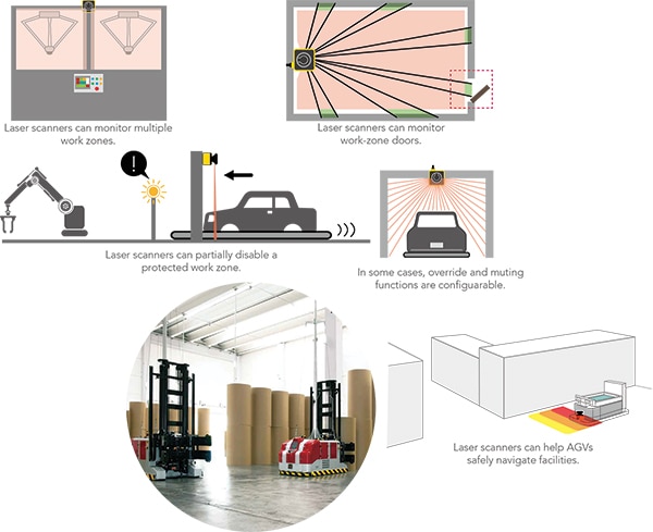 Figure 3: Laser scanners are a type of noncontact safety-feedback component best known for their helping AGVs navigate facilities. However, their applications abound — and they can sometimes offer an alternative to light curtains. (Image source: IDEC)
Separate from personnel-triggered safety-related components are those for automatic machine functions.
Built-in lockouts with latches and switches
Switches and interlocks are essential elements on the outer perimeters of machine work cells. Safety limit switches have contacts that serve to automatically verify machine element positions or motions. In contrast, safety switches with higher functions — those called interlock safety switches — use tongue or hinge interlock mechanisms as tamper-resistant machine guards having positively driven (double-verifying NO and NC) switching contacts. Trapped-key interlock switches with mechanical keys and locks keep doors into machine workspaces closed until access is safe. Increasingly common though are noncontact RFID and magnetic safety switches that monitor the position (open or closed) of work-zone doors and disallow operator access during hazardous processes.
Built-in safety with electrical breakers and isolators
Safety components triggered by machine status also include those to ensure electrical safety. Circuit breakers (much like fuses) protect against the detrimental and dangerous effects of overload currents on mains, power branch, and signal circuits. Some installations include isolators for galvanic separation between field devices and controls to ensure intrinsically safe operation. Complementing all designs for electrical safety are surge-protective components to prevent voltage spikes from damaging electrical and electronic automation components involved in mains and drive power and/or feedback and control-signal distribution.
Built-in mechanical safety with brakes
Brakes that qualify as safety brakes are also called failsafe brakes. These default to a stopped state (typically to lock or hold a motion axis) even if electrical or fluid power fails or is removed. All rely on spring-loaded or other mechanical action for this failsafe operation.
Case in point: Spring-set friction brakes that are pneumatically released often serve as failsafe brakes in servomotor-driven automation applications. All must carry a rating that certifies compliance with ISO 13849-1 — typically from the international product-testing organization Intertek Group. Thanks to their mechanical locking, these consume no electrical power while holding … which provides maximum reliability for safety-grade performance and avoids overheating associated with other electrically based modes of stopping. Life is rated in millions of cycles before common cause (predictable) failure to some percent of all components in the series. Where IIoT functionality is useful, failsafe brakes can also include onboard diagnostics and sensor feedback to track operational status.
Brakes having the highest functional safety ratings incorporate multiple springs that mechanically lock machine axes via friction surfaces that interact with stationary elements inside the brake housing. Safety standards also require inclusion of sensors to confirm brake status.
Safety relays and other safety controls
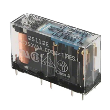 Figure 4: Simple equipment needing just a handful of safety I/O can economically employ electromechanical safety relays such as this one. (Image source: Omron Automation and Safety)
Supporting the functions of safety switches, sensors, and guards are safety relays and other controls. All share a common ability to (when needed) take the machine to a safe state through the removal of electrical or fluid power — or slow or lock a still-powered machine into a safe condition.
Relays for hardwired safety
One option for failsafe control is safety relay modules. These employ electronics with short-circuit and overvoltage protection as well as complementary relays. Hardwired electromechanical relays have been used for decades; they simply wire into automated controls and (in conjunction with emergency stop or light curtains) electrically disconnect machine subsections as needed. Drawbacks include the need for extensive wiring onsite and a lack of reconfigurability. More advanced safety relays sport I/O and a modular design to facilitate flexible integration with sensors, machine controls, and automation networks.
Safety controllers for programmable safety
Another option for safety that qualifies as failsafe is the integration of dedicated safety controllers. Such controllers are more suitable than relays for complex automation systems because they can serve larger I/O arrays as well as PLC functions. The one caveat is that these standalone safety controllers necessitate additional programming and personnel training. However, their digital electronics allow for automation functions that are fully configurable via software.
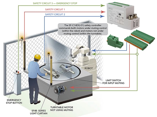 Figure 5: Safety controllers can unify multiple safety functions for flexible and reconfigurable safety installations. In the workcell illustrated here, the first safety circuit includes a light curtain that (upon reporting an interrupted status) opens a circuit switch to stop the turntable. The second safety circuit integrates muting controls that let the robot operate normally if a workpiece enters the workcell when the turntable is stopped. Otherwise, this circuit opens a switch to disable the robot. The third safety circuit includes an emergency stop that opens all switches and stops both turntable and robot. (Image source: Panasonic Industrial Automation Sales)
Engineers can define zones needing safety coverage and modify their settings without the need to rewire the entire workcell. (That in turn trims wiring hardware and labor costs.) Usually, safety-controller-based installations also support network expansion and IIoT connectivity as operations evolve.
Integrated safety on safety-rated industrial controls
A third option for failsafe safety control that’s increasingly common in sophisticated machinery is integrated safety PLCs, programmable automation controllers (PACs), and other PC-based controls. Some such electronics hardware can assume safety functions in addition to everyday machine functions. The result is programmable and therefore flexible control over both automated machine equipment and the safety functions their operations require.
Conclusion
Sufficient machine safety relies on feedback and control components rated to provide protections commensurate with a given application’s hazards. Machine safety also requires proper component integration, documentation, and validation. The latter ensures safety circuits work correctly for all machine operation modes, even during faults.
IEC 61508 and 62061 safety-lifecycle standards define how safety integration is correctly executed — from initial risk assessment and design to real-world verification of an installed system’s performance by the OEM and again by or for the end user once the machine is installed. The latter puts machines “through the paces” with tests of normal operation sequences, slowdowns, stops, and reset routines.

Disclaimer: The opinions, beliefs, and viewpoints expressed by the various authors and/or forum participants on this website do not necessarily reflect the opinions, beliefs, and viewpoints of DigiKey or official policies of DigiKey.


