Choosing and Applying the Optimum DC/DC Converter for Medical Applications
Contributed By DigiKey's North American Editors
2024-12-06
Designing a power supply that runs off AC mains or battery power is complicated. The designer must develop a solution that provides a stable voltage and current across varying loads while operating efficiently to minimize power dissipation. However, when the power supply is intended for a medical product, the design becomes more complicated due to electromagnetic compatibility (EMC), strict safety requirements regarding electrical contact with a patient, and protection from electromagnetic interference (EMI).
Meeting these requirements is costly and time-consuming for designers developing medical power supplies from the ground up. Commercial modular DC/DC converters are an alternative, but care must be taken when selecting and applying these solutions.
This article briefly describes the role of a DC/DC converter in a power supply circuit and outlines the selection criteria and special considerations demanded for medical applications. It then introduces example devices from XP Power and shows an application model.
The role of a DC/DC converter
While batteries are rated with a nominal voltage, the output is affected by factors such as state of charge, peak demand, and temperature. A key characteristic is that voltage output declines as the battery discharges. Yet, ICs and other sensitive components require a steady voltage to function correctly. A DC/DC converter offers a solution by regulating the input voltage to provide a reliable and consistent voltage output (or outputs) to power the end product.
DC/DC converters are common in mains-powered products, too. An initial AC/DC converter regulates the AC mains to a DC voltage with one or more DC/DC converters. Then, further regulation brings that voltage to a suitable level for the end-product.
Topologies for DC/DC converters can be linear or switching. Linear regulators are simple and robust devices, but their efficiency declines as the difference between input and output voltage increases. Also, linear regulators can only step down (buck) rather than step up (boost) or invert a voltage. Not being able to boost voltages leaves untapped potential in batteries.
Switching regulators use a switching element that is pulse width modulated (PWM) and typically comprises one or two MOSFETs paired with one or two inductors and capacitors for energy storage and filtering. The main reasons designers choose switching regulators are high efficiency and high power density. Moreover, the regulators can boost, buck, and invert voltages.
The challenges for designers using switching regulators include design complexity, cost, and potential EMI issues due to the switching elements. It is possible to design a DC/DC switching regulator from scratch, and such an approach can save some cost and space, but it is complex and time-consuming. An alternative is to select from the wide range of commercial modules, such as XP Power’s JMR series, that integrate the primary elements of the switching regulator into a single device that is compact, reliable, and easy to design into a product (Figure 1).
 Figure 1: Modular devices such as the JMR series integrate the primary elements of a DC/DC switching regulator into a single device that is compact, reliable, and easy to design in. (Image source: XP Power)
Selecting a DC/DC converter
There are many factors to consider when choosing a DC/DC converter. Some are obvious; for example, the application will determine input and output voltages and input and output current. Others are more nuanced. For example, maximizing efficiency requires consideration of the typical load profile of the end product. Also, the designer should examine the datasheet efficiency curves for the shortlisted DC/DC converters to ensure the end product generally operates at the converter’s efficiency sweet spot.
XP Power’s JMR1024S05 is a good example of a DC/DC converter for a medical application. This converter is an ultra-compact, printed circuit board (pc board) mount medical device measuring 20.3 x 31.8 x 10.2 millimeters (mm), with 3 mm through-hole leads. It has an output of 5 V from a nominal input of 24 V (min 9 V, max 36 V). The module features a maximum output current of 2 amperes (A) and a full-load input current of 491 milliamperes (mA). The output ripple voltage is 75 millivolts (mV) peak to peak (pk-pk), and its efficiency is 84.9%.
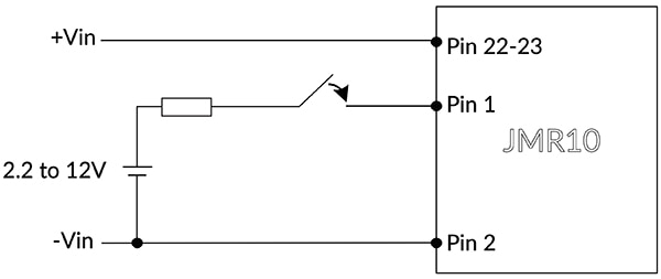
The module features a low no-load power consumption of 6 mA, which boosts efficiency and lowers power dissipation. A further no-load power consumption savings of 3 mA can be made by remotely inhibiting the module (Figure 2). The module is on if Pin 1 is an open circuit; the module is off if Pin 1 is connected to a current source of 2 mA to 4 mA, or if 2.2 V to 12 V are applied to Pin 1 relative to Pin 2.
 Figure 2: The no-load power consumption of the JMR1024S05 can be reduced to 3 mA by remotely inhibiting the module. (Image source: XP Power)
XP Power offers alternatives in their 10 watt line. The JMR1048S12, for example, operates from a nominal 48 V input (18 V to 75 V) and delivers a 12 V output with a maximum output current of 833 mA. The full-load input current is 237 mA, and when operating in this condition, efficiency is 88%.
The JMR1012D15 operates from a nominal 12 V input (4.5 V to 18 V) and delivers a ±15 V output with a maximum current of 333 mA. The full-load input current is 957 mA, and when operating in this condition, efficiency is 87%.
The switching frequency for the JMR 10 watt series is 300 kilohertz (kHz).
Special requirements for medical applications
Medical products demand more from a DC/DC converter because electrical components used in the end products are subject to the strict IEC 60601-1 medical safety standard.
According to IEC 60601-1, the “applied part” is defined as the element of the medical device that comes into direct contact with a patient, or has parts that are likely to come into contact with the patient during the product’s normal use. The standard defines applied parts according to the type of patient contact and the nature of the medical device.
Type B classification is given to applied parts that are generally nonconductive and may be connected to ground. Type BF (body floating) is given to applied parts that are electrically connected to the patient and must be floating and separated from ground. Type BF does not cover applied parts with direct contact to the heart. Type CF (cardiac floating) classification is given to applied parts suitable for direct heart connection. Type CF applied parts must be floating and separated from ground.
Patient-connected medical devices are required to provide means of protection (MOP) to prevent applied parts (and other accessible parts) from exceeding the limitations of voltage, current, or energy. A compliant protective ground connection provides 1 x MOP, basic isolation also provides 1 x MOP, and reinforced insulation provides 2 x MOP.
MOP can be further categorized as Means of Operator Protection (MOOP) and Means of Patient Protection (MOPP). In devices intended for patient connection, 2 x MOPP are required.
Power supplies for medical devices with Type BF and CF classifications must provide 2 x MOPP from primary to secondary and 1 x MOPP from primary to ground. Additional safety isolation from any secondary output of the power supply to ground must also be rated at 1 x MOPP for the highest-rated incoming AC line voltage. Table 1 shows air clearance, creepage distance, and test voltages for basic (1 x MOP) and reinforced (2 x MOP) insulation in both MOOP and MOPP applications.
| |||||||||||||||||||||||||||
Table 1: Shown are the air clearance, creepage distance, and test voltages for basic (1 x MOP) and reinforced (2 x MOP) insulation in both MOOP and MOPP applications. (Table source: XP Power)
In addition to MOP for MOOP and MOPP applications, the power supply for a medical device must be designed to limit the touch current, patient auxiliary current, and patient leakage current. The maximum allowable values for the touch current are 100 microamperes (μA) in normal conditions and 500 μA in a single fault condition (SFC). This requirement effectively limits the system ground leakage current to 500 μA in normal operation.
The requirements for touch current, patient auxiliary current, and patient leakage current represent a challenge for designers. They must ensure that the power supply provides the required safety isolation while minimizing leakage currents under normal operation and protection under fault conditions by isolating the patient from the ground.
Finally, the medical device must comply with the EMC requirements outlined in IEC 60601-1-2. These requirements aim to improve the immunity of equipment from the many wireless communication devices operating close to life-critical equipment. The secondary objective of the requirements is to provide EMC guidance for equipment used outside of the hospital when there tends to be less control over the EMC environment.
Using a DC/DC converter as a second isolation stage
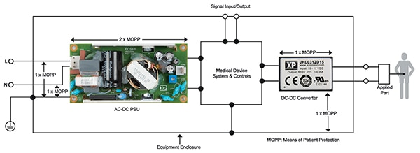
The design challenges of special medical requirements can be mitigated by carefully selecting a DC/DC converter to introduce a second isolation stage. The addition of this stage provides basic isolation at AC line voltage. It also minimizes input-to-output capacitance (to around 20 to 50 picofarads (pF)), which in turn reduces the potential patient leakage current to just a few microamperes (Figure 3).
 Figure 3: An approved DC/DC converter (right) can be used for voltage regulation to the applied part while providing secondary isolation for 1 x MOPP and minimizing potential patient leakage current. (Image source: XP Power)
For example, the XP Power JMR series 10 watt DC/DC converters described above feature IEC60601-1 medical safety agency approval, 2 x MOPP 5 kilovolt (kV) AC reinforced isolation, 17 pF isolation capacitance, and 2 μA patient leakage current, enabling easy integration into a wide range of BF and CF medical applications.
EMC filtering, required to enable the end product to meet the requirements of IEC 60601-1-2, can be added to the circuit between the medical device system and controls and the DC/DC converter without compromising isolation or low-leakage currents. Figure 4 illustrates recommended EMC filter circuits for surge and electrical fast transient (EFT), and EMI Class B.
 Figure 4: Shown are recommended EMC filter circuits for surge and EFT and EMI class B for use with JMR10 series DC/DC converters. (Image source: XP Power)
Table 2 shows recommended component values for these circuits when using the JMR10 series devices with input voltages of 12 V, 24 V, and 48 V.
|
Table 2: Shown are the recommended component values for the circuits shown in Figure 4. (Table source: XP Power)
Conclusion
Modular and highly integrated DC/DC converters simplify the design of reliable, high-performance power supplies for medical systems. Still, designers must carefully choose a device with IEC 60601-1 certification to ensure it meets the standard’s requirements for operator and patient safety, as well as EMC.

Disclaimer: The opinions, beliefs, and viewpoints expressed by the various authors and/or forum participants on this website do not necessarily reflect the opinions, beliefs, and viewpoints of DigiKey or official policies of DigiKey.


