Build a MEMS Vibration Sensor System for Condition-Based Monitoring in Industrial Applications
Contributed By DigiKey's North American Editors
2019-08-27
Any piece of industrial machinery will eventually fail, either sooner due to manufacturing imperfections or later due to accumulation of debris, deterioration of internal parts, or just wear and tear. With the growth of automated industrial lines, factory operators face a seemingly endless cycle of maintenance and repairs that can bring the line to a standstill, particularly when undetected faults in machinery turn into catastrophic failures.
Rather than coping with unexpected equipment failures or enduring unnecessary downtime for unwarranted maintenance, plant operators can use condition-based monitoring (CBM) indicators to more efficiently schedule maintenance and repairs well before equipment enters a critical operating state. The ability to monitor a machine’s operational state can translate into significant savings in an industrial environment. By detecting conditions that typically precede equipment failure, industrial engineers can repair machinery before it fails.
In implementing CBM, however, the nature of the conditions that need to be monitored can differ, requiring developers to build accurate sensor signal chains that match their specific requirements.
This article discusses requirements for implementing CBM for industrial equipment and describes how developers can build signal chains capable of meeting these requirements using a combination of devices from Analog Devices.
Vibration analysis
Underlying CBM methods, vibration analysis has become the predominant technique for assessing the operating state of machinery and its moving parts. In this approach, industrial engineers analyze vibration measurements to identify patterns that indicate imbalance, misalignment, or damage to rotors, gears, bearings, and any other mechanical interfaces between machine components. For example, repeated patterns of high amplitude vibrations can reflect mechanical shock events due to damaged or worn clutches, gears, bearings, bearing races or other contacting machine surfaces.
Beyond this time domain vibration measurement, however, frequency domain measurement using fast Fourier transform (FFT) analysis can provide even greater detail about the machinery state. Although the FFT calculations used to generate this frequency domain analysis require more computing horsepower, the result is well worth the effort. Using this approach, experienced engineers have found several reliable frequency related indicators of such faults as imbalance, misalignment, looseness, and bearing defects, among others (Figure 1).
 Figure 1: By measuring the absolute and relative magnitude of peaks in the frequency domain, industrial engineers can deduce a wide variety of current and potential machinery problems ranging from machine part imbalance to bearing failures. (Image source: Analog Devices)
Among these indicators, changes in the fundamental frequency, also called the 1x component, relative to its harmonics and earlier baseline 1x measurements can signify some imbalance in the machine, reflected in a signal whose amplitude is proportional to the square of the rotational rate, and whose frequency matches the machine's rotational or resonant frequency. In contrast, misalignments or looseness between parts of a machine cause a characteristic increase in the first harmonic, also called the 2x component, and even in frequency components as high as 10x. Similarly, imbalanced, misaligned, or damaged internal parts such as gears result in higher peaks at frequencies related to their own rotation rate and number of teeth.
Fault indicators can become quite complex, particularly for bearings buried in races within a machine. As bearings move through their race, they generate a characteristic signal at a frequency called the ball spin frequency (BSF), contained within an envelope related to the bearing race's fundamental train frequency (FTF)—the rate at which the bearing cage travels around the bearing. Defective bearings or races result in a relatively higher amplitude event at the BSF, resulting in a train of low amplitude vibrations modulated by the FTF (Figure 2).
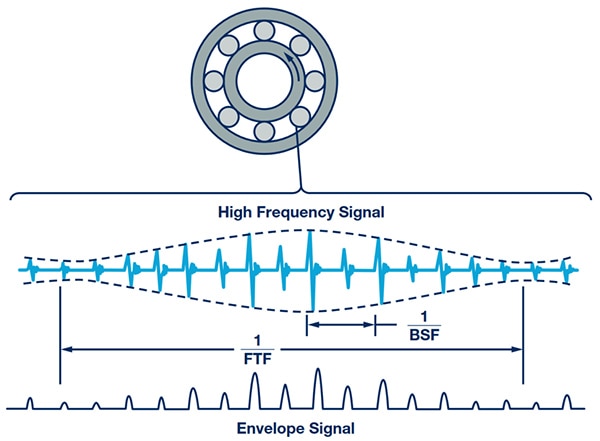 Figure 2: Vibration signatures associated with machinery faults can range from easily recognized peaks at the fundamental frequency and a few harmonics, to complex signatures for bearing faults that modulate pulses at the ball spin frequency (BSF) with an envelope signal related to the bearing race's fundamental train frequency (FTF). (Image source: Analog Devices)
The resulting frequency domain signature of bearing faults can be quite complex, appearing as a broad increase in low amplitude components spread across a wide high frequency band (see the right side of Figure 1).
Despite the apparent complexity of frequency domain signatures, industrial engineers have developed an extensive catalog of analysis methods and detailed indicators to diagnosis faults ranging from imbalances and misalignments to more subtle bearing related problems.
Analysis and vibration measurement methods continue to increase in sophistication due to greater demand and availability of more effective solutions. In the past, engineers have typically used handheld vibration monitors with portable data loggers to record patterns for later offline analysis.
The move to Industry 4.0 automation and increased reliance on automated machinery has made manual methods less practical. With the availability of more advanced semiconductor devices, CBM applications are increasingly based on vibration measurement devices attached directly to critical machinery to offer continuous monitoring.
Vibration measurement requirements
As with any sensor signal acquisition application, vibration measurement devices for CBM rely on a familiar signal chain topology comprising a sensor, a signal conditioning stage, an analog-to-digital converter (ADC), and a processor (Figure 3).
 Figure 3: Vibration sensing systems use a familiar topology that combines a signal chain comprising a sensor, a low-pass filter (LPF), an operation amplifier, and an ADC with a processor and support devices. (Image source: Analog Devices)
To support the kind of frequency domain analysis mentioned earlier, the specifications of this vibration signal chain typically differ significantly from the signal chains used for motion detection in consumer devices.
One of the most critical differences between industrial and consumer applications lies in their vibration sensor bandwidth requirements. As noted above, fault indicators in machines can appear in harmonics that are 5x or even 10x that of the fundamental frequency or broadly across an even higher frequency band. Industrial machines routinely operate at hundreds or even thousands of revolutions per minute (rpm), so a machine operating at 1,000 rpm can require a vibration sensor with a 5 kilohertz (kHz) or greater bandwidth to enable capture of spikes at frequencies associated with bearing faults or complex misalignments. Similarly, a wide bandwidth is necessary to capture signals associated with bearings operating at their higher BSF ranges.
Wide bandwidth performance alone can be insufficient to capture more subtle fault signatures associated with small imbalances, misalignments, or problems with bearing races or the bearings themselves. Although small in amplitude, these signal sources can reflect emerging problems or even imminent failures in the case of bearing problems. Consequently, CBM vibration measurement devices also need to operate with a low noise floor and with sufficient resolution to isolate the low amplitude signals associated with these faults.
Microelectromechanical systems (MEMS) sensors
Although piezoelectric accelerometers were frequently used in industrial applications in the past, microelectromechanical systems (MEMS) sensors have more recently emerged as an effective solution. Fabricated on a silicon substrate, these polysilicon structures are based on cells comprising a moveable plate between two fixed plates (Figure 4).
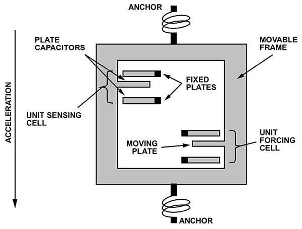 Figure 4: Fabricated with conventional semiconductor process technologies, a microelectromechanical systems (MEMS) sensor incorporates cells of fixed and movable plates that deflect in response to acceleration, resulting in changing cell capacitance. (Image source: Analog Devices)
When acceleration causes the movable plate to deflect relative to the fixed plates, the differential capacitance changes, producing a sensor output that is proportional to the acceleration.
Even with their small deflections, advanced MEMS vibration sensors support the high-performance ranges needed to track the acceleration associated with industrial machinery.
According to the equation for simple harmonic motion, acceleration is related to frequency as follows:
a = -(2pf)2x (Equation 1)
Where:
a = acceleration
f = frequency
x = the amplitude of the displacement from the central position (typically on the order of 1 micrometer (µm) in MEMS vibration sensors)
As a result, the acceleration experienced by a MEMS sensor for industrial machinery can reach hundreds of gs—orders of magnitude greater than the acceleration ranges experienced by MEMS vibration sensors commonly used in consumer products (Figure 5).
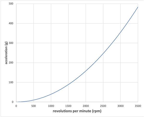 Figure 5: MEMS sensors can experience very high acceleration at ranges of revolutions per minute, typical of industrial machinery. (Image source: DigiKey from Analog Devices data)
Thanks to continuing advances in MEMS fabrication technologies, developers can now find MEMS vibration sensors such as those in the Analog Devices ADXL100x family of MEMS accelerometers that not only meet the stringent requirements for vibration-based CBM applications, but also simplify design of the underlying vibration sensing systems.
Integrated MEMS sensors
The Analog Devices ADXL100x family of MEMS single-axis vibration sensors, including the ADXL1001, ADXL1002, ADXL1003, ADXL1004, and ADXL1005, provide developers with a range of devices able to meet industrial requirements for acceleration range, bandwidth, resolution and noise (Table 1).
|
Table 1: Performance specifications of Analog Devices ADXL100x vibration sensors (Table source: Analog Devices)
Because they are fabricated with conventional semiconductor process technologies, MEMS sensors can easily be integrated with other circuits to provide a variety of analog and digital functions. Each member of the ADXL100x family uses the same functional architecture, combining the MEMS sensor with a sensor amplifier, a demodulator, an output amplifier, and additional features (Figure 6).
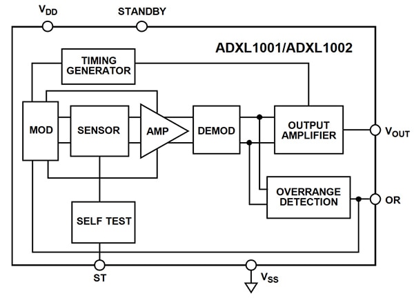 Figure 6: All members of the Analog Devices ADXL100x family of vibration sensors combine a MEMS sensor with a comprehensive sensor signal conditioning stage as well as additional functional capabilities. (Image source: Analog Devices)
Among these features, an overrange (OR) detection capability helps protect the sensor element when acceleration exceeds about twice the device's specified g range. Such events are not uncommon in normally operating machinery, particularly when a machine first starts up or later changes speeds. Until it stabilizes at its fundamental frequency, the combination of resonating frequencies generated as its components come up to speed could oversaturate even the most robust vibration sensor.
When an overrange condition occurs, the ADXL100x OR subsystem sets the OR output signal to warn the host processor. In addition, it disables the internal clock for 200 microseconds (μs) to prevent damage to the MEMS structure. If the overrange continues past this 200 μs period, the OR subsystem retriggers the output signal and shutdown period every 500 μs.
Building out the signal chain
The integrated output amplifier of the ADXL100x can drive resistive loads up to 2 milliamps (mA) of source current with a maximum load capacitance of 100 picofarad (pF). Consequently, developers could in principle connect their ADXL100x directly to an Analog Devices AD4000 16-bit precision successive approximation register (SAR) ADC.
In practice, the use of this direct-connect configuration requires a sample rate of at least 220 kHz. This sample rate requirement arises due to the need to sample at twice the 3 decibel (dB) frequency response bandwidth of the device, which is well above that of the MEMS sensor (see Table 1). In fact, the integrated output amplifier is designed with a 3 dB frequency response bandwidth of 70 kHz to allow measurements at frequencies approaching the sensor's resonance frequency, which can be significantly higher than the 3 dB frequency provided in the specifications (Figure 7).
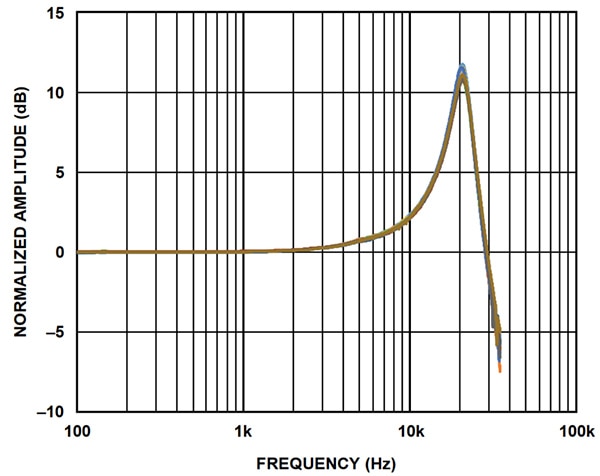 Figure 7: Analog Devices’ ADXL100x family of vibration sensors provide a wide bandwidth frequency response similar to the curve shown here for the ADXL1002, which specifies a 3 dB bandwidth of 11 kHz and exhibits a characteristic resonance frequency peak at a significantly higher frequency band. (Image source: Analog Devices)
As with any conversion signal chain, the sample rate needs to be at least twice the equivalent noise bandwidth (ENBW) to avoid the inclusion of noise aliasing into the frequency band of interest. Since ENBW = π/2 x ω3dB, where ω3dB is 70 kHz in this case, the ENBW for ADXL100x devices is 110 kHz. Thus, the required sampling rate must be at least 220 kHz.
Developers can easily reduce this sampling requirement with the simple addition of a single-pole, low-pass filter. In fact, Analog Devices recommends using a two-pole resistor-capacitor (RC) filter between the sensor and an ADC, such as the previously mentioned Analog Devices AD4000 (Figure 8).
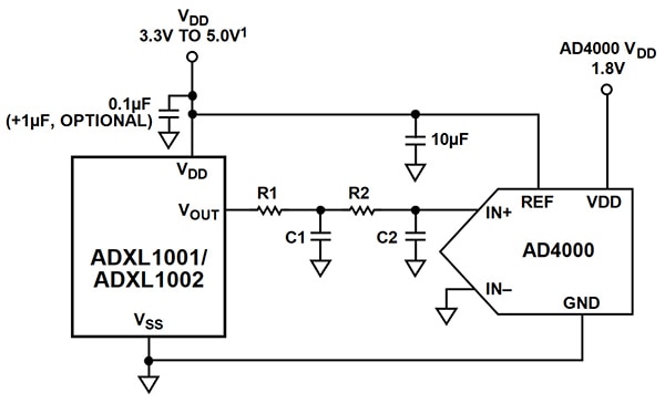 Figure 8: Developers can reduce the required sensor sampling rate by using a simple two-pole low-pass filter between an Analog Devices ADXL100x MEMS sensor and an Analog Devices AD4000 ADC. (Image source: Analog Devices)
For example, using a 16 kiloohm (kΩ) R1 resistor, a 300 pF C1 capacitor, a 32 kΩ R2 resistor, and a 300 pF C2 capacitor would provide an attenuation of about 84 dB at the 200 kHz internal clock frequency of the ADXL1001/ADXL1002. In this case, an ADC sample rate of 32 kHz would be sufficient to measure vibrations from 0 to 10 kHz without aliasing artifacts.
Using the ADXL100x sensor with the AD4000 ADC and only a few passive components, developers can implement a complete signal chain for vibration measurement. The core of a vibration sensor system design can be quickly completed with the addition of a voltage regulator such as the Analog Devices ADP7104 low-dropout (LDO) regulator, a reference voltage source such as the Analog Devices ADR4550, and a processor such as the Analog Devices ADUCM4050 microcontroller.
Using these few components with different members of the ADXL100x family, developers can meet specific performance requirements such as greater acceleration range or higher bandwidth associated with their unique CBM application.
Three-axis measurements
For more complex CBM applications, the single-axis measurement capability of the ADXL100x family might be insufficient. Although developers could easily replicate their basic design for each required measurement axis, Analog Devices provides a simpler approach with its ADcmXL3021 triaxial vibration sensor module.
The Analog Devices ADcmXL3021 module is enclosed in a 23.7 millimeter (mm) x 27.0 mm x 12.4 mm aluminum housing with mounting flanges, and supports three-axis measurement using three ADXL1002 MEMS accelerometers positioned along mutually orthogonal sensing axes (Figure 9).
 Figure 9: The Analog Devices ADcmXL3021 module is contained within a 23.7 mm × 27.0 mm × 12.4 mm aluminum housing (left) and provides a complete three-axis vibration measurement system (right) able to meet industrial performance requirements. (Image source: Analog Devices)
Within each MEMS sensor's signal chain, a dedicated ADC samples at 220 kilosamples per second (kSPS), storing results in the module's built-in first-in, first-out (FIFO) buffer. The module's integrated processor supports time domain and frequency domain measurements with four different operating modes:
- Real-time streaming (RTS), which provides real-time data
- Manual FFT mode (MFFT), which generates frequency domain data in response to a trigger from an external signal or software command
- Automatic FFT mode (AFFT), which uses an internal timer to automatically trigger frequency domain data capture
- Manual time capture (MTC) mode, which captures 4,096 consecutive time domain samples and supports use of signal processing functions including filtering and averaging
With its integrated MCU, the ADcmXL3021 offers additional capabilities beyond its four sampling modes. One such capability supports industry standards such as ISO 10816, which calls for the use of warnings when a machine enters an unsuitable operating condition and alarms when the machine enters a critical condition.
In MTC mode, the ADcmXL3021 provides alarms with three different configurable levels (normal, warning, and critical) for the time domain data. To support ISO 10816 notifications, developers can set signals indicating normal level, warnings signals indicating unsuitable operations, and alarm signals indicating unsafe operations.
For frequency domain measurements in MFFT or AFFT modes, the ADcmXL3021 provides a more sophisticated alarm capability. Here, developers can configure six alarm band configurations, each specifying upper and lower frequency range as well as upper and lower amplitude. Using this capability, developers can configure the ADcmXL3021 to recognize specific frequency and amplitude signatures associated with known warning or alarm conditions (Figure 10).
 Figure 10: Developers can configure the Analog Devices ADcmXL3021 vibration sensor module to issue warnings or alarms using a combination of indicators based on vibration magnitude and vibration frequency band. (Image source: Analog Devices)
To help simplify development with the ADcmXL3021, Analog Devices provides its ADCMXL_BRKOUT breakout board that provides headers for easier access to the ADcmXL3021 flex tail connector pins.
Analog Devices also provides a Windows-based ADCMXL Vibration Evaluation software application designed to work with the Cypress Semiconductor CYUSB3KIT-003 USB 3.0 SuperSpeed Explorer Kit. Using the evaluation software interface, developers can examine time domain and frequency domain data for each axis and modify ADcmXL3021 registers to explore alternative capture configurations (Figure 11).
 Figure 11: Developers can use an Analog Devices evaluation software application to view output from the ADcmXL3021 vibration sensor module or interactively modify its registers to explore different capture configurations. (Image source: DigiKey/Analog Devices)
Conclusion
CBM can provide substantial advantages for avoiding unnecessary scheduled maintenance or unscheduled downtime due to sudden machine failure. For developers of CBM applications, however, the strict performance requirements of suitable vibration measurement systems can be daunting. Unlike motion detection sensing systems in consumer applications, industrial vibration systems require high acceleration range, wide bandwidth, high resolution, and very low noise density. Using MEMS sensors and associated components from Analog Devices, developers can confidently create the kind of robust vibration measurement systems required to implement sophisticated industrial CBM applications.

Disclaimer: The opinions, beliefs, and viewpoints expressed by the various authors and/or forum participants on this website do not necessarily reflect the opinions, beliefs, and viewpoints of DigiKey or official policies of DigiKey.


