Basics of Safety Interlocks
Contributed By DigiKey's North American Editors
2022-11-10
Keeping plant personnel safe requires that they be protected from mechanical threats to bodily harm. This field of safety engineering is called industrial risk reduction. Local laws and industry standards legally require that automated equipment include various mechanical safety features to prevent dangerous machine startups and trigger safe shutdowns should a new risk of personnel harm arise. The foundation of these safety systems are well-defined boundaries around the machine — and safeguarding or machine-guarding components.
Though safeguarding is a term casually used in some literature, standards from the International Organization for Standardization (ISO) and an increasing number of automation component suppliers assign it a very specific definition. These authoritative industry sources generally limit guarding to mean components and subsystems surrounding possibly dangerous segments of equipment with:
- Sheet-metal housings and chain-link or glass fencing
- Sliding glass panels, doors, and swinging gates
- Sensors and light curtains
- Specialty barrier components of other electronic or physical design
- Safety interlocks — the focus of this article
Though guarded machine perimeters mostly consist of immovable elements, the movable or penetrable sections mentioned (including window shields, curtains, and doors) can allow operator access at strategic locations for machine tending, adjusting, or servicing. A convenient way to categorize these safety components is to group them by whether machine operator or other plant personnel make direct physical contact with that safety component (as with light curtains, for example) or whether some intermediate machine subsection contacts the component. The latter include an array of machine-activated safety switches and sensors as well as interlocks.
 Figure 1: On each of this machine’s doors, limit switches verify closure before allowing the machine to startup. (Image source: Getty Images)
So, what exactly are interlocks? They are mechanical, electrical, or electromechanical safety components that are at their core a proximity or position switch. They always install on machine confines at moveable (penetrable) gates. Unlike safety curtains or operator switches, interlocks are those that are triggered through the movement of either movable machine or perimeter sections. To be clear though, safety interlocks can be triggered by actuated perimeter sections or those that are manually opened. Their name derives from the way they inter-lock (and render interdependent) allowed safety-controller conditions and perimeter-gate positions … whether open or closed or something else. In other words, interlocks provide feedback to safety controllers that in turn elicit the correct machine status for a given set of machine-guard positions.
Standards governing the inclusion of interlocks
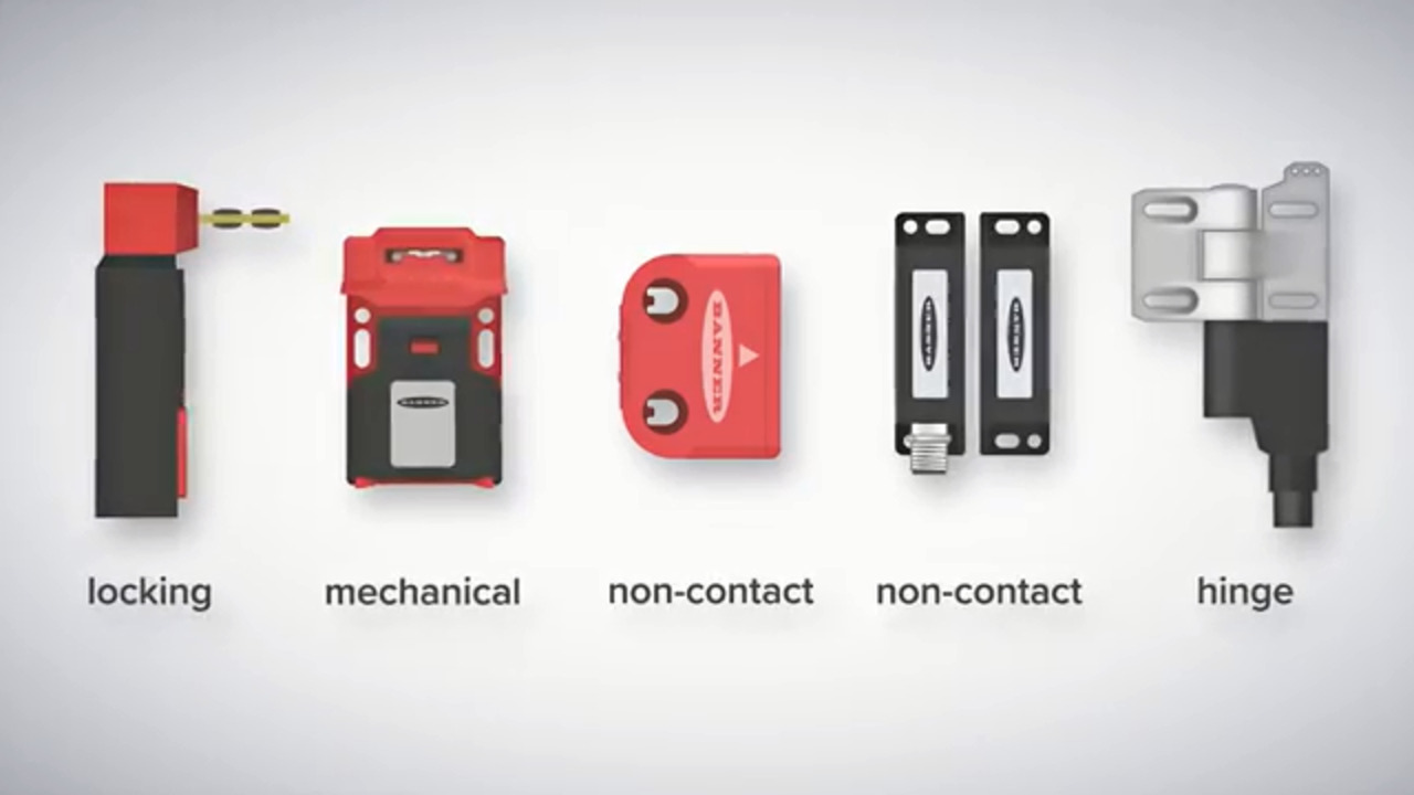
") Figure 2: Interlock switches can accommodate various orientations. International safety standards define the classifications of such interlock variations. (Image source: Design World)
Figure 2: Interlock switches can accommodate various orientations. International safety standards define the classifications of such interlock variations. (Image source: Design World)
Currently, the design and integration of interlocks of industrial-automation applications must satisfy five full standards — including Conformitè Europëenne (CE) Machinery Directive 2006/42/EC. ISO 12100 (and adopted ISO 14119 passages) define interlocks as devices that prevent hazardous machine operations when gates into the guarded area are open. The interlocks called guard locks or locking gate switches that go a step further to latch gates closed are subject to their own requirements — including the requirement that they feature an escape latch for technicians who find themselves locked inside a dangerous work cell.
Some of the standards reference the core position switch or proximity-switch technology at the core of every interlock. They also outline the requirements of how electronically actuated workcell guard sections network with equipment controls — typically to command any potentially dangerous motions to slow or even cease.
Accommodating time for machine to stop
The most dependable interlocks satisfy specific axis-stop intervals — defined as the time a machine requires to slow to a safe state after issuance of a stop command. In fact, interlock systems accommodate for these stop intervals as well as the time in which it’s feasible that a machine operator could reach hazardous axes after issuance of a stop command. Optimized interlock installations:
- Ensure a safe state is achieved long before an operator could ever possibly touch or approach dangerous machine axes.
- Support efficient machine use by avoiding excessively long lockdown states.
In fact, ISO 12100 details how interlock-guarded doors and panels can (with their closing) immediately trigger resumption of machine operation. That’s in contrast with emergency stops that necessitate more involved machine-restart sequences. The logic of such standards is that the use of interlocks is routine (so shouldn’t hinder every day operations) but that of e-stops is not.
Core interlock technology and defeatability
Automated machines must satisfy Type A, B, and sometimes C international safety requirements. The functional-safety ISO 12100-1 standard and other foundational Type A standards apply to all automation equipment. Electronic controls satisfying ISO 12100 can address situations involving any unavoidable maintenance of some energy source — namely by preventing any unexpected machine restart. For this purpose, e-stops are never acceptable solutions ... but key interlocks can be.
Type B midrange standards include B1 safety-approach standards (including ISO 13849-1 and 62061) as well as specific B2 safe-system requirements (including ISO 13850 and 13851). In contrast, Type C standards are very specific to machine types, so are particularly stringent and most employed by OEMs for new equipment design.
Standards specific to interlocks are ISO 14118 and 14119.
ISO 4118 details ways to prevent unexpected machine startups (by dissipating mechanical power and cutting electrical power) upon an operator’s entry into a hazardous machine workspace. Such systems can disconnect power supplies, stop motors, release fluid power actuators, and allow the spending of any remaining kinematic energy of the machine’s moving segments.
In contrast with other standards mentioned in this article, ISO 14119 covers the required specifics of guard interlocks by:
- Referencing the risk-analysis techniques of other safety standards.
- Defining interlock features that prevent accidental and intentional safety defeats.
ISO 14119 defines Type 1 interlocks as position switches using easily defeatable mechanical hinge or cam actuation. Actuating contact occurs between interchangeable (uncoded) halves. Benefits of Type 1 interlocks are low cost and high configurability.
Type 2 interlocks (as first defined by DIN EN 1088) include less circumventable position switches based on mechanical actuation. Halves are coded (mated) tongues or (for safety guard locks) trapped keys. The latter force operators to lock all guards before controls allow machine startup … and key removal is only possible when the guards are latched. Fully integrated perimeter controls go even further to force operators to use those same keys in keyed HMI start switches that hold the key captive during machine operation.
ISO 14119 classifies all noncontact safety switches sans coded actuation as Type 3 interlocks. The most easily defeated are those employing optical, ultrasonic, or capacitive actuation; slightly less defeatable are induction and magnetism-based interlocks. Where defeatability is unacceptable, Type 4 interlocks which use matched or coded actuator halves in noncontact operation whether based on RFID, magnetic, or optical technology) are warranted.
Comparing interlocks with safety sensors and perimeter switches
 Figure 3: The mere closing of guard interlocks doesn’t trigger the restart hazardous machine processes; instead, those honors go to a separate double-duty control interlock or start switch like the soft-touch capacitive finger switch shown here. (Image source: Getty Images)
 Figure 4: Some doubly capable interlocks have actuators to function as guard locks. These are position switches with deadbolts or electromagnetic assemblies that can keep doors barred until the guarded robotic arm or machine ceases its hazardous motion. Unfortunately, some engineers mistakenly believe that all interlocks are of the guard-lock variety. (Image source: Omron)
Interlocks share similarities with other safety-rated feedback and sensing components based on the same core technologies. But to be clear, none of these other components are associated with machine perimeters like interlocks. In addition, today’s safety standards require that interlocks won’t greenlight resumption of action sans some corrective reversal process.
Components supplied as industrial safety sensors verify (often via noncontact inductive or photoelectric means) machine element or workpiece positions for controllers to command responses suitable for the reported conditions. In contrast, industrial safety switches turn power supplies off and on upon detection of machine element or workpiece positions. Upon verification of the trigger positions, such switches either prompt disconnection or resumption of power to the related machine section. No more is it sufficient to use an ordinary proximity switch as an interlock. Demanding IEC 60947 requirements now demand that components used as interlocks have very specific safety-related features to prevent defeats and other failures.
Also found in safety systems are relays that directly make or break electrical contacts — in the most common arrangements, essentially communicating a small command voltage onward to ultimately spur a larger current through the power contacts it commands. Consider two common functions that interlocks render interdependent: the opening of a guard door and a motor-driven spindle on a machine tool. Mutuality between these renders the milling station unlikely to damage its own subsystems or injure the operator. In this regard, interlocks function as switches in an operational sequence.
Most rare are mechanically cammed interlocks with arms that pivot on an axis to lock dangerous machine axes. Far more common are electromechanical and electronic interlocks employing circuits and microprocessors for cost-effective reliability and even reconfigurability. For example, electromechanical hinged interlocks on perimeter doors include a mechanical elbow or lever arm that opens with the hinged guard; beyond the set switching angle, it triggers commands to stop the perimetered machine. Upon door reclosing, the door force ultimately prompts the interlock’s solenoid to reclose the circuit.
Typical wiring and solenoid types in interlocks
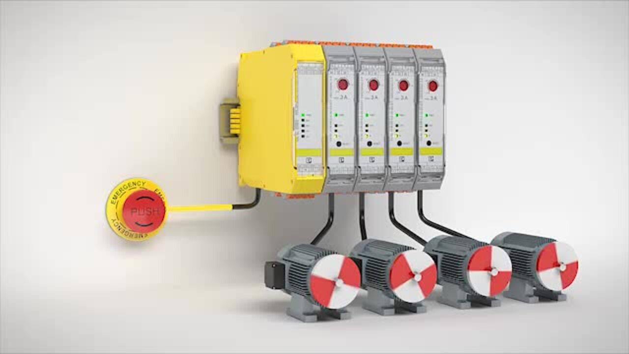
") Figure 5: Innovative connectivity options have only increased the reliability of multi-guard installations in recent years. Here, an interface module is connected via T-adapter networks to other safety components. (Image source: Banner Engineering)
Figure 5: Innovative connectivity options have only increased the reliability of multi-guard installations in recent years. Here, an interface module is connected via T-adapter networks to other safety components. (Image source: Banner Engineering)
Interlocks are most commonly wired for normally closed or NC logic to only let machines run if the circuit is closed. Most safety standards require that safety-circuit components wire in series for maximally reliable error and event detection (up to an allowable sensor total). Exceeding that number of sensors can degrade a design’s performance level (PL) and increase the likelihood of fault masking.
Safety interlocks employing one spring-actuated NC switch (whether position or limit) typically deliver positive breaking — so that opening the guard presses against the interlock’s spring to spread its electrical contacts apart. In contrast, more reliable twin-switch interlocks use one switch to actuate upon guard opening and another switch with electrical contacts spread apart upon guard closing. Electronic self-reporting of shorts (usually by monitoring the potential difference between two input channels) is a complementary feature to detect severing of wires due to shearing, corrosion, or overheating.
The reliability of plunger-and-coil solenoid operation renders solenoid-based safety components suitable for critical interlock applications. Electrical input typically causes linear plunger output (with a spring-set return upon power off). When integrated into guarding and deadbolting interlocks, solenoids are the input source for the latching mechanisms. Other such solenoid-based designs can also ensure correct mechanical operation — for example, to ensure consistent conveyor travel even when tending equipment handle or process workpieces riding its belt. Solenoid-based redundancies (with series-wired and double-pole switches for verifying position) can minimize faulty interlock signaling.
Conclusion
Interlocks render machine perimeter status interdependent with safety controls. In fact, today’s interlock feedback to such controllers can spur exceptionally sophisticated machine responses to various machine-gating positions. The most advanced interlocks can assume failsafe edge computing, IIoT, and reliability tasks beyond the capabilities of traditional industrial switches and sensors. The main caveat is that guard interlocks mustn’t be cumbersome to machine operators. Automatic functions and conditional unlocking on the most frequently accessed guard doors can improve functionality with minimizing undetected faults.
Disclaimer: The opinions, beliefs, and viewpoints expressed by the various authors and/or forum participants on this website do not necessarily reflect the opinions, beliefs, and viewpoints of DigiKey or official policies of DigiKey.