Non-Isolated PoE Powered Device Power Supply
Analog Devices' non-isolated PoE powered device power supply features robust operation in adverse environments
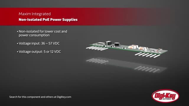
 Many PoE applications are isolated to protect both people and systems from voltage and current transients. However, many applications do not require isolation such as LED lighting and other equipment generally out of range for human touch. In these cases, eliminating the isolation circuitry further reduces cost and power dissipation at the PoE point-of-load.
To meet the increasing demands for non-isolated Power over Ethernet (PoE) power solutions, Analog Devices has developed innovative, non-isolated PoE powered device (PD) power solutions. These non-isolated PoE power solutions efficiently convert high-voltage PoE power into 5 V or 12 V outputs. Each design was tested for load and line regulation as well as efficiency and transient performance. As with all Analog Devices reference designs, the BOM, schematics, layout files, and Gerber files are all available. In addition, boards are available for purchase. These boards feature a module architecture with through-hole pins for immediate board placement and accelerated prototyping.
MAXREFDES98# and MAXREFDES108# combines the PD controller and the step-down converter on a 14.0 mm (0.55 in.) x 55.9 mm (2.2 in.) board. The module accepts input voltages ranging from 36 V to 57 V, and provides an output voltage of 5 V with current capacity of 2.5 A or 12 V with current capacity of 1 A, respectively. Both products feature twelve through-hole pins spaced at a 2.54 mm pitch standard. This modular architecture allows MAXREFDES108# or MAXREFDES98# to be soldered into a PCB or inserted into the MAXREFDES98EV# for evaluation.
The reference designs contain all the control circuitry and electric components required for designing a 36 V to 57 V wide-input, 5 V / 2.5 A (12.5 W)(MAXREFDES98#) or 12 V / 1 A (12 W)(MAXREFDES108#) output, non-isolated, step-down converter power supply.
The circuit consists of two function blocks: the PD controller and the step-down DC-DC converter. The PD controller section employs the MAX5969A. Following the PD controller is the step-down DC-DC converter. This circuit employs the MAX17505 (MAXREFDES108#) or MAX17503 (MAXREFDES98#), Analog Devices’ high-efficiency, synchronous, step-down DC-DC converter with internal compensation.
| Features | ||
|
|
|
| Applications | ||
|
|
|
| Resources | ||
|
||
Reference Design Kits
| Image | Manufacturer Part Number | Description | Voltage - Output | Available Quantity | Price | View Details | |
|---|---|---|---|---|---|---|---|
 |  | MAXREFDES108# | EVAL BOARD FOR MAX5969A MAX17505 | 12V | 1 - Immediate 15 - Factory Stock | $334.20 | View Details |
|  | MAXREFDES98# | EVAL BOARD FOR MAX5969A MAX17503 | 5V | 1 - Immediate 8 - Factory Stock | $334.20 | View Details |
Associated Product
| Image | Manufacturer Part Number | Description | Power - Output | Available Quantity | Price | View Details | |
|---|---|---|---|---|---|---|---|
|  | MAXREFDES98EV# | EVAL BOARD FOR MAX5969A MAX17503 | 12.5W | 0 - Immediate 119 - Factory Stock | $586.52 | View Details |
|  | MAX17505ATP+ | IC REG BUCK ADJ 1.7A 20TQFN | Buck | 4689 - Immediate 900 - Factory Stock | $35.27 | View Details |
| | MAX17503ATP+ | IC REG BUCK ADJ 2.5A 20TQFN | Buck | 8200 - Immediate | $39.79 | View Details |
| | MAX17503ATP+T | IC REG BUCK ADJ 2.5A 20TQFN | Buck | 7465 - Immediate | $39.63 | View Details |