Make a Quick Start on Wireless Design with Microchip’s Curiosity Board
Although wireless connectivity is ubiquitous and getting easier for consumers to use, designing wireless projects is still daunting if you have limited experience in RF engineering.
Commercial modules, which typically incorporate embedded processors, transceivers, RF tuning circuits, power management, and even an antenna or two, make the job easier because much of the RF design and testing has been done. However, some prototypes need attention to additional design details to ensure success even when using a module, such as the WBZ451PE-I from Microchip Technology (Figure 1).
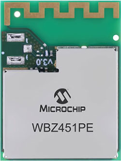 Figure 1: The WBC451PE-1 module makes building wireless products more accessible, but pitfalls remain for the unwary. (Image source: Microchip Technology)
Simple things like the orientation of the module on the board, the placement of ground planes, electromagnetic interference (EMI) shielding, the location of other components, printed circuit (pc) board trace impedance, and many other factors come into play. So much so that a well-designed wireless product with an RF module can exhibit greater range, higher throughput, and lower power consumption, relative to one where the designer didn’t pay as much attention to detail.
Time to code
Software will also play a significant role in the overall product performance. A wireless product typically demands both an RF protocol stack and application software.
While it’s possible to write the code for RF protocol software such as Bluetooth Low Energy (LE), Zigbee, or proprietary 2.4 GHz protocols, proven and mature stacks are typically supplied by the transceiver maker or available from open-source libraries. This is probably the most cost-effective and quickest way forward.
Transmitting radio packets across a wireless link is one thing; ensuring they carry a useful payload is quite another. The application code determines the type, priority, format, and how often data is transmitted, among other parameters. The software might do something relatively simple, such as send temperature, humidity, or heart rate information. More complex applications might demand the transmission of audio streams or multiple real-time frequencies from machine vibration sensors.
The RF protocol and the application software can impact the product performance as much as the hardware. For example, poorly written application code might result in a constant interruption of the RF protocol stack, compromising throughput. Or the application software might detrimentally impact the duty cycle of the radio. For example, it might instruct the radio to transmit data more frequently than needed, unnecessarily increasing power consumption.
Getting help for a wireless project
The good news is that there are plenty of places for you to turn to for help when embarking on a wireless project. Manufacturers are only too keen to assist with hardware design, protocol, and application software examples.
Hardware help often comes in the form of evaluation kits, which can be complete working designs based on the target wireless transceiver or module. Silicon vendors often helpfully offer pc board Gerber files and a bill of material (BOM) specifying the evaluation kit’s components, making it easy to use the product as a hardware reference design. A vital part of the evaluation board design is the antenna positioning. You’ll need adequate clearances from ground planes and other components to ensure optimum antenna sensitivity. By using a manufacturer’s layout, you can avoid compromising antenna performance.
Microchip Technology’s EV96B94A WBZ451 Curiosity Board is an example of a complete evaluation kit (Figure 2). The evaluation board makes it easier for engineers to prototype Bluetooth LE and Zigbee projects for smart home and industrial automation applications. At the heart of the Curiosity Board is the IWBZ451PE-I Bluetooth transceiver module. This module is based on the PIC32CX-BZ2, a general-purpose, low-cost, 32-bit microcontroller that can support multiprotocol wireless interfaces such as Bluetooth LE (up to version 5.2) and Zigbee (up to version 3.0), while also managing an RF transceiver and power management unit (PMU).
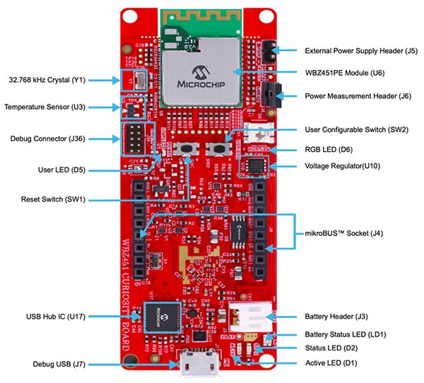 Figure 2 : Top- side view of the EV96B94A Curiosity Board with the WBZ451PE-I module at the toptip. Note the built-in clearances for the pc board antenna on the module to ensure optimum performance. (Image source: Microchip Technology)
The WBZ451PE-I module incorporates the microcontroller and supports either a pc board antenna or a u.FL connector for an external antenna. The module is equipped with a set of standard microcontroller peripherals, such as an analog-to-digital converter (ADC), and interfaces such as Serial Peripheral Interface (SPI), Inter-Integrated Circuit (I2C), Quad SPI (QSPI), and Universal Asynchronous Receiver-Transmitter (UART).
The Curiosity Board also features a Microchip external QSPI flash memory chip, an analog voltage temperature sensor, and a ten-pin Arm Serial Wire Debug (SWD) header for an external programmer/debugger.
Setting up for prototype development
You’ll find getting started with the Curiosity Board to be relatively easy. The board forms the main hardware, but you’ll also need a Type-A male to Micro-B USB cable to connect it to a PC and an Android or iOS Bluetooth-enabled smartphone. The software required for development includes the MPLAB Integrated Development Environment (IDE), MPLAB XC32 Compiler, PKOB4 Tool Pack, and an out-of-the-box demo. You can power the board from an external 5 volt supply or a 4.2 volt Li-Po battery. A hardware block diagram of the Curiosity Board is shown in (Figure 3).
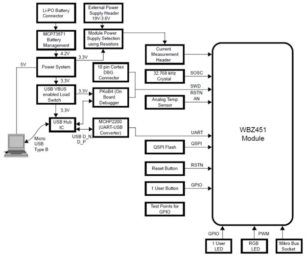 Figure 3 : A hardware block diagram of the Curiosity Board shows how the board can be powered from an external 5 volt supply or a Li-Po battery. The board also features a built-in temperature sensor and an RGB LED for use with example programs. (Image source: Microchip Technology)
The board includes an integrated programmer and debugger (part of the PKOB4 tool kit). The device supports programming and debugging of the WBZ451PE-I module from the host PC through the micro-B USB connector. By default, the on-board debugger is connected to the programming pins (SWDIO and SWDCLK) of the WBZ451PE-1 module.
The board is equipped with software that demonstrates two common Bluetooth LE and Zigbee use cases in a single application, with both interface stacks able to run concurrently. Specifically, the application supports Bluetooth LE sensor monitoring, Bluetooth LE lighting control, and Zigbee lighting control and monitoring. The sensor example implements a fully functional Bluetooth LE temperature sensor with data drawn from the Curiosity Board’s onboard temperature sensor. The board also incorporates an RGB LED.
The Zigbee lighting control software example includes full Bluetooth LE control for the RGB LED on the board. Zigbee commissioning over Bluetooth LE uses the Bluetooth LE link to exchange Zigbee commission data. Both Zigbee and Bluetooth LE tasks run simultaneously under FreeRTOS. The “Lights” in Figure 4 (represented by the RGB LED on the board) can be controlled over Bluetooth LE or from the Zigbee network. Once connected, the user can control the LED’s brightness, color, and ON/OFF state via the Bluetooth LE connection.
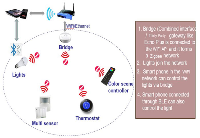 Figure 4 : The lighting control example for the Curiosity Board demonstrates the concurrent operation of Zigbee and Bluetooth LE stacks. (Image source: Microchip Technology)
After playing with the examples, you can experiment with your own code. For the inexperienced coder, Microchip offers Application Building Blocks. These compact training modules focus on the Bluetooth LE features of the WBZ451PE-I module. By moving through the building blocks, you can gain familiarity with the software, MPLAB Code Configurator, and the application programming interfaces (APIs) necessary to implement the features of interest.
Conclusion
Wireless design can be daunting for the inexperienced but is made much easier through chip vendors’ evaluation boards and RF modules. Moreover, manufacturers supply proven and reliable RF protocol stacks and make it simple to get started on application software by providing samples and building blocks upon which to base more complex applications.

Have questions or comments? Continue the conversation on TechForum, DigiKey's online community and technical resource.
Visit TechForum


