The Basics of Applying Ultrasonic Transducers for Sensing Objects or Fluid Flow
Contributed By DigiKey's North American Editors
2023-06-15
The Internet of Things (IoT) and the expanding role of artificial intelligence (AI) at the network edge have raised interest in making applications more intelligent and ambient aware. As a result, designers need to consider appropriate sensing options, many of which can rely upon well-established technologies to avoid complexity. For example, ultrasonic energy is widely used to sense the presence of nearby objects and even determine their distance, as well as to measure fluid flow rates.
The advantages of ultrasound are that it is relatively easy to apply, is accurate, has minimal safety or risk factors, carries no regulatory restrictions, and avoids radio frequency (RF) spectrum allocation, as well as electromagnetic interference (EMI) and radio frequency interference (RFI) issues.
Though well established as a methodology, to fully realize the benefits of ultrasonic sensing, designers need a good understanding of its operating principles, available components, and associated circuit requirements. They must also consider architectural approaches, such as whether to use separate transmit and receive units—which allows for placement of each in different locations—or use a combined single-unit transceiver. Finally, they must provide a suitable electronics driver and receiver which can operate at the optimal frequency for position sensing/detection and fluid flow sensing.
This article provides a basic introduction to ultrasonic transducers and their application in object detection and flow sensing. Real-world ultrasonic devices from PUI Audio are presented by way of example, and an appropriate driver IC and associated development kit are described to enable application development.
Simple principle, adopted from nature
Ultrasonic detection is a sophisticated version of the basic echolocation principle used by animals such as dolphins and bats (Figure 1).
 Figure 1: Electronic acoustic detection and position sensing has its origins in echolocation which is effectively used by living creatures such as bats. (Image source: Wikipedia)
In operation, a brief pulse of acoustic energy is generated by a transducer, which is usually a piezoelectric device. After the pulse ends, the system switches to receive mode and awaits the reflection (echo) of that pulse. When the transmitted acoustic energy encounters an impedance transition or discontinuity, such as between air and a solid object, some of that energy is reflected and can be detected, usually by a piezoelectric device.
Acoustic impedance is based on the density and acoustic velocity of a given material, and it is important to determine the amount of reflection that occurs at the boundary of two materials having different acoustic impedances.
The proportion of energy that is reflected is a function of the material type and its absorption coefficient, as well as the impedance differential at the boundary between materials. Hard materials such as stone, brick, or metal reflect more than soft materials such as fabric or cushions.
The acoustic impedance of air is four orders of magnitude less than that of most liquids or solids. As a result, the majority of ultrasonic energy is reflected to the transducer based on the large difference in reflection coefficients. The acoustic cross section is a metric analogous to radar cross section and is determined by the target object’s material and size.
This detection and distance sensing is similar to what happens when radar RF energy or lidar optical energy encounters an impedance discontinuity, and some of that energy is reflected back to the source. However, while the overall concept is the same, there is a big difference: ultrasound energy is not electromagnetic energy. Its use of the frequency spectrum is not regulated, and it has very few restrictions. One pertinent restriction is excessive sound pressure level (SPL), a consideration that is generally not relevant to sensing/detection applications, as most of these operate at fairly low power levels.
Propagation and media matter
There’s one other big difference: ultrasound sensing/detection can only be used in a propagating medium such as air, other gases, or liquids. The attenuation and propagation characteristics of acoustic energy through various media are the opposite of RF and optical energy. Acoustic energy propagates well through liquids, while RF energy generally does not. Optical energy also has high attenuation in most liquids. Further, unlike acoustic energy, both RF and optical have low attenuation in a vacuum.
In its simplest implementation, the ultrasonic system is used solely to detect the presence or absence of an object or person within an overall zone of interest by detecting a return signal of sufficient strength. By adding a timing measurement, the distance to the target can also be determined.
In more sophisticated systems where the distance to the object must also be calculated, a simple equation can be used: distance = ½ (velocity × time), using the round-trip time between the emitted pulse and received reflection, and the established speed of sound in air which is about 343 meters per second (m/s) at +20°C (+68°F). If the medium is a fluid or gas other than air, the appropriate propagation speed must be used.
Note that the speed of sound in air varies slightly with temperature and humidity. Therefore, ultraprecise distance sensing applications require that one or both of those factors must be known, and a correction factor added to the basic equation.
Interestingly, as an example of engineers turning a negative factor into a positive one, there are advanced temperature sensing systems that exploit this shift in propagation speed versus temperature. These systems measure temperature by using precise timing of the reflected ultrasound pulse reflection over a known distance. They then do a “reverse correction” to determine what temperature would have caused that change in propagation speed.
Transducer parameters start the process
After determining the application requirements, designers must then select a suitable audio driver and associated receiver that can operate at the appropriate frequency, typically at a relatively high 40 kilohertz (kHz) for position sensing/detection, and several hundred kilohertz for fluid flow sensing. The benefits of high-frequency transducers include increased resolution and focused directivity (forward-facing beam pattern), but the disadvantage is increased signal path attenuation.
The rate at which the ultrasonic energy scatters and is absorbed while propagating through the medium of air increases with frequency. This results in a decrease in the maximum detectable distance if other factors are held constant. The 40 kHz frequency is a compromise between factors such as efficiency, attenuation, resolution, and physical size, all of which are related to wavelength.
To begin the selection process, it’s helpful to know that transducers used for ultrasonic sensing are characterized by several top-tier parameters. Among these are:
- Operating frequency, tolerance, and bandwidth: As noted, 40 kHz is common for many basic applications, with a typical tolerance and bandwidth of several kilohertz.
- Drive voltage level: This specifies the voltage level for which the transducer provides optimal performance. It can range from a few tens of volts to 100 volts, or more.
- SPL: This defines the magnitude of the audio output at the defined drive level; it can easily reach 100 decibels (dB) or more. Higher SPL offers coverage over greater distances (a typical ultrasound application has a range in the tens of feet).
- Receiver sensitivity: This characterizes the voltage output of the piezoelectric transducer at a given SPL. The higher this number, the easier it will be to overcome system noise and provide an accurate reading.
- Directivity: This defines the spread of the transmitted beam as well as the angular range over which the receiver is most sensitive. Typical values range from 60° to 80° at 40 kHz, usually measured to the angle at which response is 6 dB below the value at the 0° angle.
Positioning the transducers
One of the factors that determines the choice of a transducer is the relative position and orientation of the object being sensed. If the object is directly in front of the source and all or partially at a right angle to the incident energy, some of that impinging energy will be reflected directly back to the source.
In this situation, the use of a single transducer for both transmit and receive functions (called a monostatic arrangement) can simplify physical set-up while minimizing space requirements and transducer cost (Figure 2).
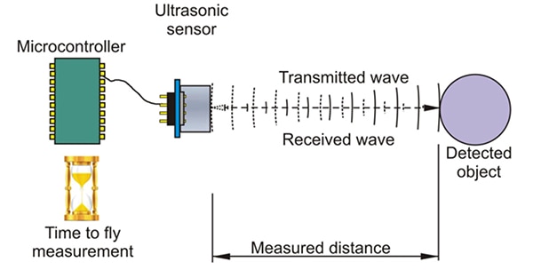 Figure 2: In a monostatic arrangement, a single transducer is used for both transmit and receive functions. (Image source: Science and Education Publishing Co.)
The PUI Audio UTR-1440K-TT-R (Figure 3), a 40 kHz ultrasonic transceiver, is a viable choice for this configuration. It has a diameter of just 14.4 millimeters (mm) and a height of 9 mm. It is designed to operate from an AC drive voltage of 140 volts peak-to-peak (Vp-p) and presents a nominal load of 1800 picofarads (pF) to the driver. Its echo sensitivity is better than 200 millivolts (mV) and its directivity is 70° ±15°.
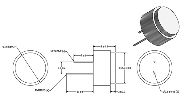 Figure 3: The UTR-1440K-TT-R is a basic 40 kHz ultrasonic transceiver that combines a transmitter and a receiver in a single housing. (Image source: PUI Audio)
In some cases, the source and receiver transducers are separate devices but are located next to each other in what is called a collocated arrangement (Figure 4).
 Figure 4: In a collocated arrangement, the ultrasonic source and receiver are located adjacent to each other. (Image source: Science and Education Publishing Co.)
Another option is to have them separated by a substantial distance and also have different orientations if the object being sensed is at an angle. This is called a bistatic configuration. In this case, the object deflects the impinging energy rather than reflecting it back to the source. Separate devices also allow for flexibility in their selection to match the application. It also allows for flexibility in the power of the transmitter’s drive circuit as it’s no longer proximal to the sensitive analog circuitry of the receiver.
For these situations, a pairing such as the 40 kHz UT-1640K-TT-2-R ultrasonic transmitter and UR-1640K-TT-2-R ultrasonic receiver may be a good choice. The transmitter measures 12 mm high and has a diameter of 16 mm. It requires just 20 VRMS drive, and it produces an SPL of 115 dB while presenting a nominal capacitance of 2100 pF and 80° beamwidth directivity. The complementary receiver has the same appearance, dimensions, directivity, and capacitance as the transmitter (Figure 5).
 Figure 5: The UT-1640K-TT-2-R ultrasonic transmitter and the UR-1640K-TT-2-R ultrasonic receiver provide different, complementary functions, but have the same form factor and dimensions. (Image source: PUI Audio)
Sensing fluid flow
Beyond basic object detection, ultrasonic transducers are used for non-invasive, non-contact measurement of liquid and gas flow rates. For these applications, the transducers operate at higher frequencies, typically above 200 kHz, to provide the needed measurement resolution.
In a typical flow application, two sensors are placed a known distance apart. The flow rate can then be calculated given the distance and the transit time that it takes for sound to travel between the two transducers in both directions, as the moving fluid carries the ultrasonic energy at different speeds in each direction.
This time difference is directly proportional to the velocity of the liquid or gas in the pipe. Determination of the flowing velocity (Vf) begins with the equation: Vf = K × Δt/TL, where K is a calibration factor for the volume and time units used, Δt is the time differential between upstream and downstream transit times, and TL is the zero-flow transit time.
Various compensation and correction factors are added to this basic equation to account for fluid temperature, and the angle between the transducers and the pipe, among other considerations. In practice, an ultrasonic flow meter requires real-world “hardware” and fittings (Figure 6).
 Figure 6: An actual transit-time ultrasonic flowmeter requires various fittings and connections; note the dual ultrasonic transducers. (Image source: Circuit Digest)
Transit-time flow meters work well with viscous liquids, provided that the Reynolds number at minimum flow is either less than 4,000 (laminar flow) or above 10,000 (turbulent flow), but has significant non-linearities in the transition region between the two. They are used to measure the flow of crude oils in the petroleum industry, and are also widely used for measuring cryogenic liquids down to –300°C, as well as for molten metal flow metering – two temperature extremes.
PUI offers ultrasonic transducers that are specifically designed for transit-time fluid flow applications. The UTR-18225K-TT operates at 225 ±15 kHz and has the narrow beam angle needed for this application of just ±15°. This transmit/receive transducer has a diameter of 18 mm and a height of 9 mm with 2200 pF of capacitance. It can be driven with a 12 Vp-p train of square waves and up to 100 Vp-p at a low duty cycle.
It also takes drive and signal conditioning circuitry
An ultrasonic detection system comprises more than just the piezoelectric transducers. Appropriate and very different circuitry is needed to meet the drive requirements of the transducer in transmit mode and for low-level analog front-end (AFE) signal conditioning in receive mode. While some users build their own circuitry, ICs are available that can conveniently provide the basic drive and AFE functions along with additional features.
For example, the Texas Instruments PGA460 is a 5.00 mm × 4.40 mm, 16-lead IC designed for use with transducers such as the PUI Audio UTR-1440K-TT-R 40 kHz ultrasonic transceiver. This highly integrated system-level IC provides an on-chip ultrasonic transducer driver and signal conditioner and includes an advanced digital signal processor (DSP) core (Figure 7).
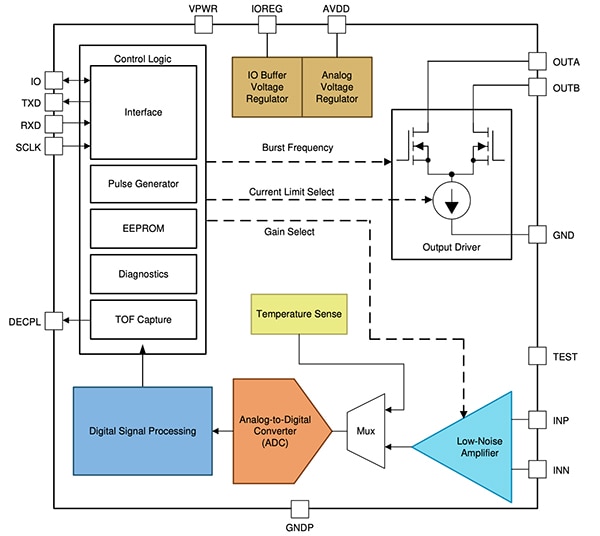 Figure 7: The PGA460 is a complete interface for both transmit and receive functions of an ultrasonic transducer. It includes power drive circuitry, an AFE, and a DSP core to run related algorithms. (Image source: Texas Instruments)
The PGA460 features a complimentary low-side driver pair that can drive a transducer either in a transformer-based topology for higher drive voltages by using a step-up transformer, or in a direct-drive topology using external high-side FETs for lower drive voltages. The AFE consists of a low-noise amplifier (LNA) followed by a programmable time-varying gain stage feeding into an analog-to-digital converter (ADC). The digitized signal is processed in the DSP core for both near-field and far-field object detection using time-varying thresholds.
The time-varying gain offered by the PGA460 is a feature often used with ultrasonic transducers, whether for basic object detection or advanced medical imaging systems. It helps to overcome the unavoidable yet known-in-advance attenuation factor of the acoustic signal energy as it propagates through the medium.
Since this attenuation and the propagation speed are both known, it is possible to compensate for the unavoidable loss by “ramping up” the AFE gain versus time, effectively cancelling the attenuation versus distance effect. The result is that the system signal-to-noise ratio (SNR) is maximized regardless of the sensing distance, and the system can handle a wider dynamic range of received signals.
To further explore the use of these transducers, Texas Instruments offers the PGA460PSM-EVM evaluation module, which works with PUI Audio’s UTR-1440K-TT-R 40 kHz ultrasonic transceiver (Figure 8).
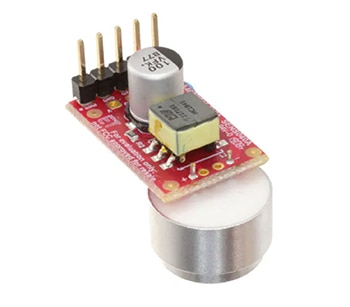 Figure 8: The PGA460PSM-EVM evaluation module is based on the PGA460 and simplifies the exploration of ultrasonic system operation using the PUI Audio UTR-1440K-TT-R 40 kHz ultrasonic transceiver. (Image source: Texas Instruments)
This module requires only a few external components plus a power supply for operation (Figure 9). It is controlled by commands received from a PC-based graphical user interface (GUI), to which it returns data for display and further analysis. In addition to basic functionality and setting of operational parameters, it allows users to display the ultrasonic echo profile and measurement results.
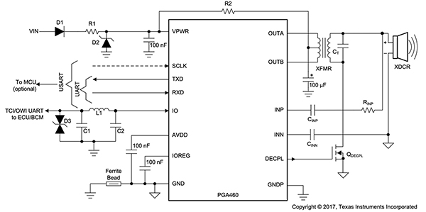 Figure 9: The PGA460PSM-EVM evaluation module connects to a PC with a GUI that allows users to operate and control the transducer and see critical waveforms, among other functions. (Image source: Texas Instruments)
Conclusion
Piezoelectric ultrasonic transducers provide a convenient and effective way to sense nearby objects and even measure their distance. They are reliable, easy to apply, and help designers avoid RF spectrum or EMI/RFI regulatory issues. They can also be used for non-contact measurement of fluid flow rates. Interface ICs for both their transmit and receive functions, supported by an evaluation kit, simplify their integration into a system while providing flexibility in the setting of their operating parameters.

Disclaimer: The opinions, beliefs, and viewpoints expressed by the various authors and/or forum participants on this website do not necessarily reflect the opinions, beliefs, and viewpoints of DigiKey or official policies of DigiKey.


