Solve Microcontroller I/O Expansion Problems by Applying External Devices
Contributed By DigiKey's North American Editors
2019-02-20
There are two microcontroller I/O problems that designers commonly face. The first is when the microcontroller that best fits an application doesn’t have the right mix of I/O capabilities. The second arises when a product line that has already been launched requires additional I/O.
In the first case, developers are often faced with having to purchase a more expensive and capable microcontroller. In the second case, the cost to switch to a new microcontroller and the porting of the software to go with it can be cost and time prohibitive.
One potential solution to both of these issues is to use external I/O expansion devices that are often connected to a microcontroller’s SPI or I2C bus. These avoid the need to over specify the microcontroller in terms of pin count and possibly performance and footprint. At the same time, this approach future proofs the product design in the face of feature creep, target market expansion, customer feature requests, and a poor microcontroller selection (it happens).
This article will discuss typical microcontroller I/O requirements and introduce some suitable external expansion devices. It will then show how to use these off-chip resources that can provide additional general purpose input and output, memory storage, pulse width modulation (PWM), and even watchdog timer functionality.
Selecting an expansion interface
Microcontrollers have several different peripheral interfaces on-chip that can be used to communicate with external devices. Depending on the microcontroller, these interfaces could be, just to mention a few:
- Serial peripheral interface (SPI)
- Inter-integrated circuit (I2C) bus
- Universal serial bus (USB)
- Universal asynchronous receiver/transmitter (UART)
- Controller area network (CAN)
- Wi-Fi
The interfaces that work best for communicating with external expansion devices are I2C and SPI.
I2C is a two-wire bus that traditionally operates at 100 kilobits/second (Kbits/s) or 400 Kbits/s, although there are some high-speed devices that support 1 Mbit/s or faster. One wire is a dedicated clock pin while the other is for bi-directional communication between a master and slave. Typically, the microcontroller acts as the master and the external devices are slaves. The slaves are addressable using either a 7-bit or 10-bit addressing scheme.
SPI is a three-wire bus interface that operates at between 1 Mbit/s and 12 Mbits/s. The SPI bus has a dedicated master out data line, a slave out data line, and a clock. Once again the microcontroller is configured to be the master device, communicating with slave devices using a “slave select” line. Every slave device connected to the microcontroller requires a dedicated output pin to select it for communication. It’s easy to imagine that if a developer has a lot of external devices they want to connect, they could quickly run out of I/O lines to select the slave devices.
For example, if a developer was using STMicroelectronics’ STM32L011D4P7, they would have eleven I/O lines to work with (Figure 1). Three I/O lines would be required just for the SPI data and clock, leaving eight lines to communicate with slave devices and perform any additional functionality needed by the system. This is perfectly fine for many applications, but at some point, the designer might need to expand the I/O.

Figure 1: The STM32L011D4P7 is an Arm® Cortex®-M0+ processor that is pin restricted with eleven I/O. (Image source: STMicroelectronics)
In general, the rule of thumb is pretty easy: use the I2C bus when adding the following capabilities:
- I/O
- PWM
- EEPROM
- Watchdog timer
The SPI bus should be used to add capabilities such as high-speed memory access to an SD card.
Expanding general purpose I/O
There are quite a few ICs that support expanding input and output through an I2C interface. A few interesting examples include:
The PCA8574 is particularly interesting because it contains only a single register for performing both input and output. A single register dramatically simplifies the amount of software that is required in order to configure the device and read and write the pins (Figure 2). The microcontroller communicates with the PCA8574 through I2C and addresses the device based on how the A0 through A2 pins are configured. This adds flexibility to the design so that a developer can choose the slave address for the PCA8574 and have several in a single design.

Figure 2: NXP’s PCA8574 is an 8 bit I/O I2C expander that is quasi-bidirectional. It has just a single I2C register to read and write to perform I/O functions on its pins, making it a very simple and sleek device. (Image source: NXP Semiconductors)
By default, P0 through P7 are configured as inputs on power-up. Reading the single internal register will give the state for each pin on the device whether it is configured as an input or an output. The PCA8574 allows the pins to act as both an input and output simultaneously, so a write to the register will set the corresponding bit’s output as well.
The output drive is pulled up by a weak internal resistor that is easily overpowered by an input value. If any of the input states change, the INT pin will toggle low to let the microcontroller know that an input state change has occurred. The microcontroller can then make an I2C call to read the new values.
Expanding PWM
A very useful expansion device is the PWM expander. This device is particularly useful when driving LEDs. When the microcontroller isn’t doing anything, it can be put to sleep and the PWM expander can be responsible for driving an LED state.
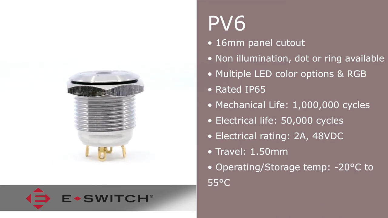
A perfect example for how the PWM expander is used often shows up in RGB push button circuits that use a PV6F240SSG RGB pushbutton from E-Switch, or a 3-101-399 SPST RGB pushbutton from Schurter Electronic Components (Figure 3).

Figure 3: Schurter’s RGB Pushbutton contains a red, green and blue LED around a push button that allows a developer to create a lit color pattern. These types of devices are perfect for being driven by a PWM expansion chip. (Image source: Schurter)
Schurter’s RGB pushbutton has a red, green, and blue LED around an SPST push button that allows a developer to create a lit color pattern. These types of applications are perfect for a PWM expansion chip.
A PWM expansion chip that’s suited for use over I2C is Maxim Integrated’s MAX7315. The MAX7315 provides eight PWM ports and includes an LED intensity control feature. This easily covers the three channels needed to drive an RGB switch, allowing a single device to drive a couple switches and some standalone LEDs. There is also a ninth port that can be used as a transition detection interrupt or as a general purpose output.
The MAX7315 I2C interface is slightly more complicated than NXP’s PCA8574 because it contains more than a single register. Developers must therefore address the slave device, provide the memory address it is interested in reading or writing, and then perform the write or read. The memory map for the MAX7315 is shown in Figure 4.
|
Figure 4: The MAX7315 PWM controller has eight output ports that include an LED intensity feature. The register map for the device is simple and allows easy access to the advanced PWM features. (Image source: Maxim Integrated)
The register map for the MAX7315 is simple and allows easy access to the advanced PWM features.
Combination expanders with WDT, EEPROM and PWM
As shown, I2C bus I/O expanders can be extremely powerful when used as standalone devices. That is, they contain only a specific function like I/O or PWM. Expanders like Cypress Semiconductor’s CY8C9520A multiport I/O expander include multiple peripheral expansions within a single IC package. The CY8C9520A comes in three varieties: 20-bit, 40-bit, or 60-bit expansion. These pins can then be configured for use as input, output, or PWM (Figure 5).

Figure 5: The Cypress Semiconductor CY8C9520 is a 20-bit, 40-bit, or 60-bit I/O expander with EEPROM. It allows the expansion pins to be configured as input, output, or PWM. (Image source: Cypress Semiconductor)
On top of the I/O expansion, the CY8C9520 also includes EEPROM that can be used to store important application settings such as a serial number, as well as other important configuration parameters.
A close look at Figure 5 reveals the WD6 pin on GPort 2. This is a watchdog timer output pin that can be used to reset the microcontroller if it fails to communicate and “pet” the CY8C9529 watchdog. The watchdog settings are completely configurable and can be used to add an extra robustness level to the application code.
Tips and tricks for expanding microcontroller capabilities
There are many techniques that can help expand a microcontroller’s capability. Below are several tips and tricks that will help:
- Use I2C to interface external devices. The interface only requires two pins and can support multiple slave devices.
- Before designing a part into hardware, purchase a development board or solder the chip to an expansion board to test if it meets all your system needs.
- Use an I2C bus tool to interface with the expansion device and learn how it works. This will dramatically speed up software development.
- Use a bus analyzer to monitor communication with the external device during software development to minimize debugging time.
- When possible, select a device that has an external watchdog timer. This can be a tool to add additional robustness to the system design.
- When interfacing with off-chip memory for data other than configuration data, use a high-speed interface such as SPI.
- Make sure that the microcontroller’s I2C driver can handle it if a device returns a negative acknowledgement (NAK) or if the bus is dragged down. It’s not uncommon for these drivers to ignore errors and enter an infinite loop if an unexpected response is received.
Conclusion
When a design reaches a point where the microcontroller no longer has any more I/O, developers don’t need to rip up their design and start back at square one. Instead, they can use external peripheral chips that allow them to add additional capabilities to their system.
Disclaimer: The opinions, beliefs, and viewpoints expressed by the various authors and/or forum participants on this website do not necessarily reflect the opinions, beliefs, and viewpoints of DigiKey or official policies of DigiKey.