How to Use Solar Cells to Power a Raspberry Pi 3 Single Board Computer
Contributed By DigiKey's European Editors
2016-07-05
Low cost single board computers such as the latest Raspberry Pi 3 are increasingly being used in headless embedded designs for monitoring and control applications. Developing applications in high-level language running on a Linux distribution with wireless connectivity integrated on the board is opening up new ways to develop and deliver innovative applications.
Delivering power to these boards has been made relatively simple through mainstream 5 V mobile phone chargers, but there is increasing interest in using energy harvested from the environment as well. This provides more flexibility for system designers to place the boards in locations that are not easily served with power lines. The power requirements of these boards are such that rechargeable batteries are not viable without an external power supply, which can be delivered via solar cells.
Using solar cells to power embedded single board computers is increasingly viable for systems that do not require a screen. As the power consumption of the devices on the boards has fallen and the efficiency of both the solar cells and the power management chips has increased, so there is the opportunity to use the cells to power the board directly and to trickle charge a battery sub-system. This allows the battery to power the single board computer and communications link for months or even years.
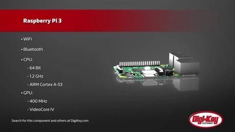
The Raspberry Pi 3 from Raspberry Pi is a key part of this move as it integrates both Wi-Fi and Bluetooth capabilities onto the board alongside a 1.2 GHz quad core ARM® Cortex®-A53 processor. This avoids the higher power consumption of using a wireless adaptor via the USB port. The board is specified to run from a maximum current of 2.4 A to support peripherals on the USB ports.
The power consumption of the board is 31 mA at idle, rising to 580 mA under load for the processor and memory. The other current load is the SMSCLAN9514 USB controller, which uses 74 mA in suspend mode. The 594 mA for the Ethernet connection is unlikely to be relevant as power can be supplied alongside an Ethernet cable.

Figure 1: The Raspberry Pi 3 board from Raspberry Pi integrates wireless connectivity.
The power consumption of the wireless connection depends on the duty cycle that is set, and this should be scheduled to start up after the main board to avoid too high a peak current requirement.
This determines the startup power requirement of around 700 mA to 900 mA, and an idle power of around 150 mA that needs to be supported by an energy harvesting source.
This can be supplied by a series of panels such as the MIKROE-651 from MikroElektronika. These panels deliver a 4 V output at 100 mA, allowing up to nine panels, each measuring 70 x 65 mm in parallel to supply the startup current. Alternatively, the 150 x 37mm AM-5902 from Panasonic delivers up to 60 mA, which would require three panels to maintain the idle power requirements.

Figure 2: The AM-5902 solar panel from Panasonic.
While two of these panels will provide idle power, this demonstrates the need for a rechargeable battery backup and a power management sub-system. The panels can then be used to trickle charge the battery to support the peak usage of the board when collecting data or sending that data to a gateway.
The rechargeable battery sub-system can be managed by a device such as the bq25504 from Texas Instruments. This is used to charge and protect the battery from discharging when the current supply from the cells fall, and can manage fluctuating sources such as energy harvesting devices.
To provide the 5 V required for the single board computer, two solar panels are connected in parallel, and connected to a rechargeable battery to provide the required current.
This needs a switch-mode step-up or -down converter and battery charger, in addition to the battery. The converter ensures that all the energy from the panels can be captured by the battery, connecting an inductor to a power source, allowing a buildup of inductor current that stores energy in the inductor. In the second cycle, a change in current path enables the inductor to transfer its accumulated energy to the load. The load voltage can be higher or lower than that of the inductor's power source.

Figure 3: Connecting the bq25504 power management chip to a battery and solar panels.
However, connecting the inductor directly to a solar panel is inefficient, so a capacitor is used. By monitoring the voltage across the capacitor, the switch-mode converter can be activated when the panel output is at its peak. The capacitor also gathers the energy from the cells when the output voltage is not high enough to start the converter, allowing all the energy to be collected and stored.
This means the converter operates in bursts when there is sufficient charge on the capacitor, allowing a fast charge of the battery. However, terminating a fast charge can be difficult, as there is no indication when the next burst of energy will come.
One approach is to monitor the output voltage with another comparator, disabling switching when the voltage reaches a high limit and enabling it when the voltage declines below a predetermined level.
The bq25504 is specifically designed to efficiently acquire and manage the output of the solar cells using a highly efficient boost converter and charger. The device starts with a DC-DC boost converter/charger that requires only microwatts of power from the cells to begin operating and can then effectively extract power.
A typical circuit is shown in Figure 3, connecting a solar panel to the bq25504 and a battery sub-system to collect the current to power the board. The bq25504 uses a battery monitoring output that can be connected to the general purpose IO pins of the Raspberry Pi 3 board. The bq25504 is mounted on an evaluation board shown in Figure 4 that can be used to provide the link between the solar cells and the battery.
Once the boost converter output, VSTOR, reaches 1.8 V to power the converter, the main boost converter can now more efficiently extract power from the solar cells. It starts up with VIN_DC as low as 330 mV typical, and once VSTOR reaches 1.8 V, can continue to harvest energy down to VIN_DC ≃ 120 mV. The integrated PFM buck converter is also powered from VSTOR and, assuming enough input power is available, provides up to 100 mA from the VOUT pin.

Figure 4: The bq25504 evaluation board can be used to power a Raspberry Pi 3 board from solar cells.
One key element of the converter is the tracking of the maximum power point (MPP) of the solar cells. This MPP varies with the amount of light on the panel and with temperature, and implements a programmable maximum power point tracking (MPPT) sampling network to optimize the transfer of power into the device. The bq25504 periodically samples the open circuit input voltage every 16 seconds by disabling the boost converter for 256 ms and stores the programmed MPP ratio of the OC voltage on the external reference capacitor (C2) at VREF_SAMP. Typically solar cells are at their MPP when loaded to around 80% of their output voltage, and while the battery is less than the user programmed maximum voltage (VBAT_OV), the boost charger loads the solar cells until VIN_DC reaches the MPP voltage. The boost charger then regulates the input voltage of the converter until the output reaches VBAT_OV, transferring the maximum amount of power to the battery. This is then used to provide the power that the board requires.
Conclusion
Connecting a 5 V single board computer with integrated wireless connectivity such as the Raspberry Pi 3 to a solar cell requires an intermediate battery and power management sub-system to provide the steady current that is required. Using a device such as the bq25504 provides the maximum power point tracking to ensure that the charging of the battery is optimized, and provides a control line back to the board. This allows the board to be used in areas where power is not available and still supply data back to the network.
Disclaimer: The opinions, beliefs, and viewpoints expressed by the various authors and/or forum participants on this website do not necessarily reflect the opinions, beliefs, and viewpoints of DigiKey or official policies of DigiKey.