How to Cost-Effectively Network Sensors for Building Management Systems
Contributed By DigiKey's North American Editors
2023-01-24
Building automation reduces the operating and maintenance costs of a facility, while also providing a safer and more comfortable environment for the building's occupants. Improvements in the performance of a building automation system (BAS) rely upon more data from an increasing number of sensors—and to an also increasing number of controls/actuators—deployed throughout a building. This deployment requires a cost-effective and efficient means of transporting the captured data from the sensing node to a central hub or cloud, where it can be analyzed and acted upon, and the required control signals delivered.
Deploying sensors and actuators at scale, particularly for legacy buildings—and where power is not readily available—can require extensive and costly rework to ensure full building coverage. To date, RS-485 networks have been a cost-effective retrofit solution, but richer data sets and higher data rates require an alternative with higher throughput.
To minimize cost while increasing throughput, designers can take advantage of currently installed single-twisted-pair Ethernet or RS-485 wiring by using 10BASE-T1L. Based on the IEEE Standard 802.3cg-2019 packet-format data-communication interface, 10BASE-T1L has a throughput of 10 megabits per second (Mbits/s) over distances up to 1000 meters (m). There is an option for the two-wire interface to also provide power via the data cable, eliminating the need for local power sources or having to route power cabling. This also eliminates the need for power-hungry gateways by being able to connect to unlimited devices.
This article discusses building control requirements and how they have been addressed to date. It then introduces 10BASE-T1L Ethernet and example solutions from Analog Devices to demonstrate its ease of implementation. It also shows how to use software I/O (SWIO) technology to simplify sensor interfacing for Ethernet network building controllers, while maintaining building management systems (BMSs) backward and forward compatibility. A suitable eval board to help designers get started with SWIO is also described.
The role of a BAS, or BMS
BASs, or BMSs, refer to the automation and management of a building's various systems. BMS objectives range from an occupant’s comfort to the building system’s efficiency, operating and maintenance costs, and security. The four layers in a BMS are the supervisory, server/application, field controller, and input/output layers.
The supervisory layer is physically the two-wire transmission layer where the supervisory devices sit. The supervisory devices consolidate all field controller traffic. The server/application receives data from different supervisory devices. This layer supports standard Ethernet protocols, such as Modbus, KNX, BACnet, and LON, commonly used in building management systems. This layer delivers the consolidated data to the client or the end user through the user interface. The field controller layer looks at input data from temperature sensors and switches and controls system outputs, such as actuators and relays.
The final piece of the BMS puzzle is the input/output layer. This layer is where the sensors and control devices exist. Some sensors and actuators support TCP/IP, which removes the need for a controller.
RS-485: A classic BMS connectivity solution
To date, the TIA/EIA-485 interface, commonly known as RS-485, has been very widely used by designers of BMS applications as it is an inexpensive local network with multidrop communication links. RS-485 is an electrical-only standard that defines the electrical characteristics of receivers and drivers when implementing a balanced multipoint transmission line. It supports a two-way, half-duplex data exchange over one twisted wire pair connection, and allows for multidrop connections (the connection of several transceivers to the same line), which is ideal for BMSs.
RS-485 also supports reasonably high data rates: 35 Mbits/s over distances of up to 10 m and 100 kilobits (kbits/s) over 1,200 m. The RS-485 rule of thumb is the speed in bits/s multiplied by cable length in meters should not exceed 10E8. Consequently, the fastest speed of a 50 m cable is 2 Mbits/s. However, it is uncommon to use such a high rate in RS-485 building control applications. The maximum speed for BACnet MS/TP, a common building automation protocol running on the RS-485 physical layer (PHY) is 115,200 bits/s).
Compared to other serial communication links, the RS-485 communication link’s main advantage is its high tolerance of electrical noise in harsh industrial environments. The RS-485 electrical noise rejection characteristic, lengthy cable runs, support of multiple transceivers on a single line, and reasonably fast data transmission speed, maps well to the BMS environment.
The 10BASE-T1L Ethernet protocol
As BMS requirements increase and datasets get richer, throughput becomes increasingly important. 10BASE-T1L provides a higher rate alternative for point-to-point communication over twisted-pair cabling, given it supports 10 Mbits/s over 1000 m. 10BASE-T1L also addresses challenges in the field, such as power, cabling, distance, and data islands, while also eliminating the need for complex gateways.
The "10" in 10BASE-T1L references the 10 Mbit/s transmission rate, "BASE" refers to baseband signals, "T" stands for "twisted pair," and the digit "1" stands for 1 kilometer (km) range. The final "L" is for "long range," indicating the segment lengths of 1 km. Able to deliver 500 milliwatts (mW), 10BASE-T1L brings Ethernet into intrinsically safe Zone 0 or hazardous area applications. In non-intrinsically safe applications, it can deliver up to 60 watts.
The topology of a 10BASE-T1L Ethernet network can be a daisy chain, line, or ring. As mentioned, there are no gateways: the Ethernet packets move from the edge to the control level, and eventually to the cloud to more fully realize the goals of seamless communications for building automation.
Whether the sensor is in a manufacturing plant or on the desk, this simplified Ethernet-to-cloud connectivity makes it possible to configure sensors with a mobile phone or laptop.
Building automation 10BASE-T1L hardware configurations
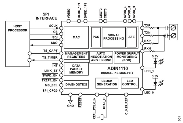
To develop a 10BASE-T1L Ethernet connectivity sensing node, designers have three ready-to-go options from Analog Devices. The ADIN1100 is a robust, industrial, low-power, 10BASE-T1L transceiver with an Ethernet physical layer (PHY); the ADIN1110 has both media access control (MAC) and PHY interface (Figure 1).
 Figure 1: The ADIN1110 is a low-power single-port 10BASE-T1L transceiver with an integrated Ethernet PHY and MAC. (Image source: Analog Devices)
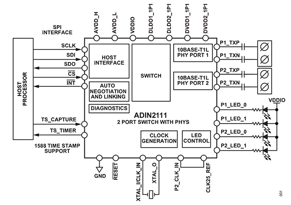
The third option is the ADIN2111, a low-power, low-complexity, two-port switch with two integrated 10BASE-T1L PHYs and one serial peripheral interface (SPI) port (Figure 2). Using SPI eases the requirements for the host processor, giving the user more choices to optimize a device for power, cost, and performance.
 Figure 2: The ADIN2111 is a low-power, low-complexity two-port switch with integrated PHYs. (Image source: Analog Devices)
The ADIN1100 and ADIN2111 10BASE-T1L devices can be deployed in a daisy chain (Figure 3), line, or ring network topology. Compared to a star network, these network topologies significantly reduce the amount of required cabling.
 Figure 3: Shown is a daisy chain topology for a 10BASE-T1L network using the ADIN1100 controller and the ADIN2111 two-port switch. Line or ring topologies can also be used. (Image source: Analog Devices)
To get started with 10BASE-T1L, designers can use the EVAL-ADIN1100 evaluation board for the ADIN1100. The board provides easy access to all ADIN1100 features and can be configured through a graphical user interface (GUI) on a PC or through standalone hardware configured operation. It includes two plug-in screw terminal connectors for 10BASE-T1L cable and an external power supply, Cat 5e Ethernet cable with RJ45 connector, and a USB-A to micro-USB-B cable. A small prototyping area is also provided.
Flexible sensor interfaces support 10BASE-T1L
At the edge of the BMS network is a complex mix of temperature, pressure, load, humidity, and strain gauge sensors that require a variety of analog circuits to capture and actuate BMS events.
To accommodate this variety of interfaces, designers can use Analog Devices’ AD74412R, a quad-channel software programmable I/O (SWIO) interface IC for process control and BMS applications. SWIO provides unique levels of flexibility for the access of any I/O function on any pin, allowing designers to configure channels at any time. The programming can occur on-the-fly through the 2-wire Ethernet channels that span an entire building. This results in fewer design resource requirements, and universal products that can be deployed quickly and broadly across an automated building.
The AD74412R contains an analog input, analog output, digital input, and the ability to perform resistance temperature detector (RTD) measurements with a compatible SPI. It is shown in Figure 4 with its 16-bit Σ-Δ analog-to-digital converter (ADC), a group of diagnostic functions, and its four configurable, 13-bit digital-to-analog converters (DACs) that provide four configurable I/O channels.
 Figure 4: The AD74412R quad-channel SWIO features four configurable, 13-bit DACs that provide four configurable I/O channels. Also included are a 16-bit, Σ-Δ ADC and a group of diagnostic functions. (Image source: Analog Devices)
The modes related to the AD74412R are current output, voltage output, voltage input, externally powered current input, loop-powered current input, external RTD measurement, digital input logic, and loop-powered digital input. The AD74412R also has a high accuracy 2.5-volt internal reference for the DACs and the ADC.
Design using the AD7441R evaluation board
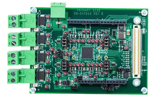
The analog applications for the AD74412R SWIO are nearly countless. To help designers get started, Analog Devices has an evaluation board, the EV-AD74412RSDZ (Figure 5). This evaluation board allows engineering exploration with onboard reconfiguration options and PC-based programmability.
 Figure 5: The EV-AD74412RSDZ is a fully-featured evaluation board for the AD74412R. (Image source: Analog Devices)
The AD74412R evaluation software communicates with the EV-AD74412RSDZ through the EVAL-SDP-CS1Z system demonstration platform (SDP) that takes input and output signals off the board. With its drop-down menu interface, it simplifies the configuration of the AD74412R and provides diagnostic tools.
Conclusion
10BASE-T1L provides for next-generation BASs with 10 Mbit/s throughput at a distance of up to 1000 m, while supporting legacy two-wire twisted pair installations. As shown, using an ADIN1100 10BASE-T1L transceiver, the ADIN2111 two-port Ethernet switch, and an AD74412R quad-channel software programmable I/O (SWIO) solution for process control and BMS applications, designers can quickly implement a 10BASE-T1L sensor network that is backward and forward compatible.

Disclaimer: The opinions, beliefs, and viewpoints expressed by the various authors and/or forum participants on this website do not necessarily reflect the opinions, beliefs, and viewpoints of DigiKey or official policies of DigiKey.


