Gesture-Based User Interface – A Step Beyond Multi-Touch?
Contributed By DigiKey's European Editors
2017-08-29
Touchscreen controls have become widely adopted throughout industry as a convenient and robust medium through which users can interact with sophisticated equipment designed to automate processes and carry out work that humans cannot do. However, a touchscreen can be impractical in situations where hygiene is a priority, such as in the food industry or healthcare, or where gloves are worn for protection.
Where workers must interact with food production equipment, contact with the surface of a touchscreen can spread contamination. Similarly, when setting up medical equipment such as a dialysis machine, the user may need to change gloves after each use of a touchscreen. In an industrial scenario where thick protective gloves must be worn, a conventional capacitive touchscreen may not respond correctly, or there could be a risk of touching the wrong button. If the glove must be removed to use the equipment, this can compromise safety and productivity.
Three-dimensional (3D) gesture recognition such as hand tracking and approach detection can interpret commands without requiring the user to touch the sensor’s surface. The ability to control equipment using natural hand and finger movements in free space can help equipment designers overcome the shortcomings of conventional capacitive touchscreens.
Optical gesture recognition, using techniques such as pattern analysis or time of flight measurements, is used in game controllers to detect whole body movement, and can be used for 3D hand gesture recognition at close range as a touchscreen alternative. However, if implementing optical gesture recognition in a control panel, holes or cutouts may be needed for light sources and detectors. Moreover, multiple sources and/or receivers may be needed, which can add cost and complexity.
Electrical near-field (E-field) sensing is an alternative approach using electrodes embedded in a front panel or integrated with a display. Various gestures can be detected, such as an approaching hand, swipes or edge flicks to control movements or make next/previous selections, and circular gestures for commands such as controlling clockwise/counterclockwise rotation.
Simplifying E-field sensing
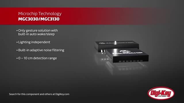
The Microchip MGC3030 gesture controller is an E-field sensing system-on-chip (SoC) with on-board processing for 3D gesture recognition and hand position tracking. It features Microchip’s GestIC® technology, which energizes an electrode using an alternating voltage at about 100 kHz to setup a quasi-static electrical near field that becomes distorted when the user’s hand or finger intrudes in the sensing area. The resulting compression of equipotential lines (Figure 1) lowers the signal levels of an array of sensors. GestIC algorithms analyze these shifts to detect proximity and interpret gestures, and use statistical modeling to distinguish between deliberate gestures and general hand movements.

Figure 1: GestIC algorithms recognize gestures by analyzing distortions in a quasi-static electrical field.
The MGC3030 runs GestIC algorithms on a 32-bit DSP core, and uses analog filtering and frequency hopping to minimize interference. The algorithms demand less intensive processing than optical gesture recognition, and combined with the MGC3030’s power-management modes including auto wake-up on approach, enable a cost-effective, low-power solution that permits always-on sensing even in battery powered equipment.
In addition to typical gestures, the GestIC suite allows touch detection including tap or double tap. An “airwheel” circular gesture is also supported, which has resolution of up to 32 counts per turn for adjusting levels, while x-y-z position tracking allows custom gestures or input sensing.
Sensor design guidelines
The design and layout of transmitter and receiver electrodes critically influences gesture recognition range, accuracy and repeatability. The MGC3030 has pins for up to five receive electrodes and one transmit electrode. The electrodes can be made of any conductive material, such as solid copper, a metal mesh, or indium tin oxide (ITO). The transmit and receive electrodes are separated by a non-conductive isolating layer, which can be made from PCB substrate, glass, polycarbonate, or a similar material. A non-conductive cover layer may also be added.
The IC’s transmitter output has a signal amplitude of 2.85 V, which is suitable for sensor sizes up to about 140 mm x 140 mm. For larger sensor sizes, up to about 200 mm x 200 mm, the output can be boosted using a level shifter operating from a supply between 5 V and 18 V provided by a system power rail or dedicated step-up converter.
Regarding the general layout of the electrodes, the sensor outline is typically square or circular, although a rectangle or oval having a ratio of no more than 1:3 is acceptable. The outline should be symmetrical about the X and Y axes if the recognition range is required to be symmetrical.
As illustrated in Figure 2, the receive electrodes are arranged at the perimeter of the sensor, and Ideally should have equal or similar lengths. Typically, the electrode width should be 5 - 7% of the length. Increasing the width increases the capacitance to the hand, which can be an advantage in weakly grounded systems such as battery powered devices, although gesture recognition range is reduced.

Figure 2: Increasing electrode width increases capacitance to the hand, but reduces recognition range.
Four electrodes are used for gesture recognition, as shown in Figure 2. The MGC3030’s fifth electrode input can be used to implement a central touch area, an external ring electrode for approach or proximity detection, or an additional touch button outside the gesture-sensing area.
The transmit electrode generates an electric field, and is located below the receive electrodes in the sensor stack, as shown in Figure 3. This positioning shields the receive electrodes and electrical connections against potential disturbance signals at the rear of the sensor. For optimum shielding, the outline of the transmit electrode should overlap the receive electrodes.

Figure 3: Cross section of two-layer sensor stack.
To minimize the effects of external noise, the transmit electrode should cover the complete area of the sensor. This is important if, for example, gesture detection is to be added to a TFT display. The designer may be tempted to arrange the sensor as a ring around the outside of the display, whereas better performance can be assured by positioning transparent electrodes such as a thin layer of ITO above the display.
The MGC3030 gesture controller should be positioned as closely as possible to the electrodes, although away from the user’s most likely approach direction. A suitable solution is to mount the IC on the backside of the sensor PCB. This may be either within the sensor area or close to the outside edge, as shown in Figure 4.

Figure 4: Chip placement and electrode connections.
The conductors connecting the receive electrodes and the IC input pins are sensitive to the user’s hand and to environmental disturbances, and so should be kept as short as possible and away from any external interference sources. In addition, to ensure stable and consistent operation, conductors that are mechanically fixed, such as PCB tracks and/or board-to-board connectors, are preferable to flexible connections such as cables that may move while the sensor is operating.
The sensor’s performance is also influenced by the dielectric properties of the isolating layer between the receive electrodes at the top of the stack and the transmit electrode underneath. If the PCB is used for isolation, the relative permeability of standard FR4 (εr = 5) requires a thickness of at least 1.0 mm. Increasing the thickness to 1.5 mm - 2.0 mm will significantly improve the performance. A glass insulator (εr = 6) should be at least 1.2 mm thick, while plastics, which have typical εr of about 3.0, can be as thin as 0.6 mm.
In addition to the electrode layers and isolating layer, a ground layer is also required in battery operated systems. In earth grounded systems, an additional ground layer is optional, and can be implemented to increase stability and minimize sensitivity to disturbances at the rear of the sensor.
If a ground layer is used, it should be implemented as a third layer below the transmit electrode. In this case, the maximum capacitance permissible between the transmit electrode and ground is limited by the IC’s transmit output capability and must not exceed 1 nF. If necessary, various techniques can be used to reduce the capacitance, including changing the isolator for a material of lower permeability, increasing the separation distance between the transmit electrode and ground, using a mesh electrode rather than a solid one, or inserting an external voltage follower between the IC output and the transmit electrode to act as a driver.
Detailed design assistance
Although GestIC technology helps engineers implement gesture recognition quickly and easily, correct design of the sensor has a critical influence on operating range and sensor stability. Table 1 describes common problems that can result from poor sensor design, with likely causes and solutions.
|
Table 1: E-field sensor troubleshooting guide.
For further information, refer to the Microchip GestIC Design Guide, which provides comprehensive advice on electrode design, material selection, board layout, managing system capacitances, and designing boosting and driving circuitry.
Conclusion
E-field sensing provides a convenient way of implementing 3D gesture recognition as an alternative to a touch-based user interface. Microchip’s GestIC technology simplifies implementation and can recognize a variety of gestures suitable for controlling industrial or medical equipment. An additional touch sensor can be implemented if required. Taking the time to understand basic sensor design guidelines can help optimize performance and reliability, and reduce time to market.
Disclaimer: The opinions, beliefs, and viewpoints expressed by the various authors and/or forum participants on this website do not necessarily reflect the opinions, beliefs, and viewpoints of DigiKey or official policies of DigiKey.